9-15
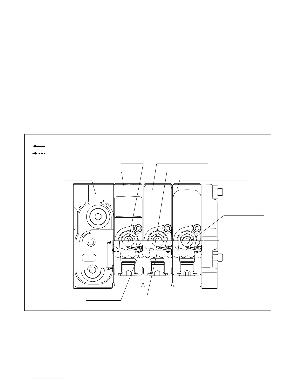
4. Load sensing mechanism
The pressure compensation valve, unload valve and sensing circuit are part of pressure compensation
operation.
When the spool strokes, chamber 7 connects to each cylinder port.
Sensing pressure is the cylinder pressure, which gives feedback to the pressure compensation valve.
When sensing pressure + pressure of spring (2) = pressure of chamber (d) and chamber (c), the
pressure compensation valve moves to the equilibrium position.
The pressure differential between the sensing pressure and chamber (d) and chamber (c) becomes
the pressure of spring (2).
The pressure of chamber (d) and chamber (c) is applied to the unload valve, then the unload valve
moves to the equilibrium position, when pressure of chamber (e) and chamber (c) + pressure of spring
(1) = P port pressure.
The pressure differential between chamber (d) and chamber (c) and P port pressure becomes the
pressure of spring (1).
The force of spring (1) and spring (2) is now constant, so the pressure differential is constant, and
sensing pressure + force of spring (1) +force of spring (2) = P port pressure.
Load sensing mechanism
7
Main flow/excess flow
Pilot flow
Inlet section
LS check valve
Lift section (1st spool)
Attachment section (3rd spool)
Attachment spool
Tilt spool
Lift spool Tilt section (2nd spool)
 Loading...