9-20
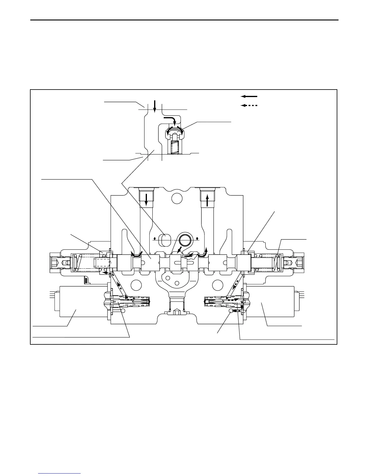
9. Attachment operation
When you operate the attachment lever, solenoid b3 is energized and the solenoid proportional valve
moves to the left. Then the pressure oil controlled by the pressure reduction valve flows to chamber (r)
on the left side and the spool moves to the right side.
Now the oil from chamber (s) drains out from 10 via the solenoid proportional valve.
The flow of the pressure oil after this is the same as for tilt operation.
Attachment operation (attachment section)
(a)
VV
10
(s)
(r)
Main flow/excess flow
Pilot flow
Tilt section
Load check
Outlet
Section V-V
Port C4 Port C5
Attachment spool
Solenoid b3
Electromagnetic proportional valve
Electromagnetic proportional valve
Solenoid a3
Spring 9
 Loading...