EasyManua.ls Logo

Toyota CQ-TS6670LC User Manual

Toyota CQ-TS6670LC
35 pages
To Next Page IconTo Next Page
Page #1 background imageLoading...
Page #1 background image
General
Power Supply DC 12V (10.5V - 16V),
Test Voltage 13.2V
Negative Ground
Current Consumption 3A or less (0.5W output)
Power Output 17.5W×4
Dark Current 0.3mA or less
AM Radio
Frequency Range LW: 153 - 279kHz
MW: 522 - 1,611kHz
Usable Sensitivity LW: 40dB(µV) or less
MW: 34dB(µV) or less
Signal to Noise Ratio LW: 22dB or more
MW: 21dB or more (35dB(µV))
MW: 42dB or more (74dB(µV))
CQ-TS6670LC
CQ-TS6671LC
AM/FM/RDS MPX ELECTRONIC
TUNING Radio with CD Player
TOYOTA PART No. : 86120-05110(CQ-TS6670LC)
86120-05120(CQ-TS6671LC)
ID CODE : W58830 (CQ-TS6670LC)
W58831 (CQ-TS6671LC)
VEHICLE : AVENSIS
DESTINATION : Europe
PRODUCED AFTER : Mar., 2006
NOTE: CQ-TS6670LC is black while CQ-TS6671LC is
silver.
FM Stereo Radio
Frequency Range 87.5 - 108MHz
Usable Sensitivity 14dB(µV) or less (S/N 30dB)
Signal to Noise Ratio 35dB or more (18dB(µV))
46dB or more (54dB(µV))
RDS Radio
RDS Sensitivity 22dB(µV)
CD Player (YGFD15314)
Channel Separation 60dB or more (1kHz BPF)
Signal to Noise Ratio 65dB or more (IHF-A)
Dimensions** 178×100×151.4mm (W×H×D)
Weight** 2060g
* Specifications and the design are subject to possible
modification without notice due to improvements.
** Dimensions and Weight shown are approximate.
Specifications*
Question and Answer IconNeed help?

Do you have a question about the Toyota CQ-TS6670LC and is the answer not in the manual?

Toyota CQ-TS6670LC Specifications

General IconGeneral
ModelCQ-TS6670LC
CategoryCar Stereo System
TypeCD Receiver
Supported MediaCD, MP3, WMA
DisplayLCD
BluetoothYes
USB PortYes
Aux InputYes
CompatibilityToyota vehicles
Output Power50W x 4

Summary

Audio Component Specifications

Main Unit Block Diagram

Main/Display Block Architecture

Presents the overall functional block diagram of the main and display units.

Terminal Descriptions

Main Block Terminal Functions (IC600)

Details the purpose and I/O characteristics of each terminal on the main block integrated circuit.

Integrated Circuit Diagrams

Main Block IC Diagram

Provides package information and a block diagram for the main unit's integrated circuits.

Main Block Wiring Diagrams

Main Block Top View Wiring

Illustrates the wiring layout on the top side of the main printed circuit board.

Main Block Bottom View Wiring

Illustrates the wiring layout on the bottom side of the main printed circuit board.

Schematic Diagrams

Main Block Schematic

Provides a detailed circuit schematic for the main unit's electronic functionality.
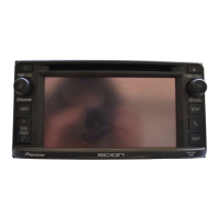
Related product manuals