Do you have a question about the Toyotomi GAG-A240GVR and is the answer not in the manual?
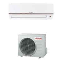
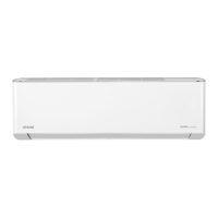
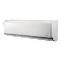
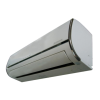
Details the indoor unit models GAN-A180GVR and GAN-A240GVR.
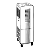
Details the outdoor unit models GAG-A180GVR and GAG-A240GVR.
Shows the remote control window YB1F2.
Key instructions for safe installation and operation to prevent injury.
Explains the meaning of warning and caution symbols used in the manual.
Precautions for electrical work, grounding, and wiring.
Safety advice for unit placement, tubing, and environmental factors.
Detailed technical specifications for both 18K and 24K models.
Specific technical data for the outdoor units.
Graphs showing current vs. compressor speed for cooling and heating.
Graphs illustrating capacity changes based on outdoor temperature.
Tables detailing operational data under specific conditions.
Graphs showing noise levels at different fan speeds and frequencies.
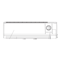
Diagrams showing indoor unit dimensions and wall mounting frames.
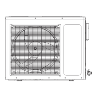
Diagrams showing outdoor unit dimensions and required installation clearances.
Diagrams illustrating the refrigerant system for 18K models.
Diagrams illustrating the refrigerant system for 24K models.
Lists electrical symbols, parts names, and color codes.
Shows the electrical wiring schematic for the indoor unit.
Shows the electrical wiring schematic for the outdoor unit.
Identifies and explains the functions of each button on the remote controller.
Details operations for mode selection and temperature adjustment.
Explains swing functions, turbo, sleep, and timer operations.
Instructions for replacing remote controller batteries and important notes.
Describes the unit's display indicators and their meanings.
Explains how to operate the unit using the manual switch.
Detailed explanation of cooling, dry, and fan modes for the indoor unit.
Further details on indoor unit modes and display status.
Explains protection functions and detailed control operations.
Describes specific operations like sleep function and memory.
Explains operating modes for the outdoor unit (cooling, dry, fan).
Details outdoor unit controls like compressor and fan operations.
Describes protection functions for the outdoor unit.
Crucial points for qualified personnel regarding installation.
Guidelines for selecting proper installation locations to avoid malfunction.
List of tools required but not supplied with the unit.
Detailed advice on selecting indoor and outdoor unit positions.
Steps for installing the indoor unit's mounting plate.
Procedures for boring wall holes and embedding pipes.
Detailed guide on performing correct refrigerant pipe flaring.
Instructions for connecting refrigerant pipes using flare nuts.
Guidance on connecting the drain hose properly.
Steps for connecting the electrical wiring between units.
Steps for mounting the indoor unit onto the installed plate.
Information on draining water from the outdoor unit base plate.
Connecting refrigerant pipes and tightening flare nuts.
Steps for purging air from the system using a vacuum pump.
Overall steps for conducting the final test operation.
Methods for checking refrigerant gas leaks at connections.
Procedures for checking indoor and outdoor unit operation after installation.
Exploded diagram showing components of the indoor unit (18K).
List of part numbers and descriptions for the indoor unit (18K).
Exploded diagram showing components of the outdoor unit (18K).
List of part numbers and descriptions for the outdoor unit (18K).
Safety guidelines and precautions before performing maintenance.
Steps to confirm power supply status and voltage levels.
Interpreting blinking LED indicators for primary malfunction judgment.
Detailed list of LED error codes and possible reasons.
Continued list of LED error codes and their potential causes.
Further details on LED error codes and troubleshooting steps.
Basic diagnostic steps for checking main components.
Troubleshooting guide for temperature sensor issues.
Diagnostic flowchart for indoor fan motor failure (H6).
Troubleshooting steps for jumper cap related malfunctions (C5).
Diagnosis for indoor fan circuit malfunction by zero crossing detection (U8).
Identification of key inspection points on the outdoor unit's control board.
Table of test points and their normal voltage/resistance values.
Diagnostic process for capacity charging malfunctions.
Main detection points for IPM, desynchronization, and overcurrent faults.
Diagnostic flowchart for IPM, desynchronization, and overcurrent issues.
Diagnosis for anti-high temperature and overload protection faults.
Diagnostic process for units failing to start up correctly.
Diagnostic process for compressor synchronism issues.
Diagnosis steps for overload and discharge protection faults.
Diagnosis procedure for Power Factor Correction (PFC) malfunctions.
Diagnostic steps for communication circuit malfunctions.
Flowchart for diagnosing outdoor communication circuit issues.
Table of resistance values for ambient temperature sensors.
Continued table of resistance values for ambient temperature sensors.
Table of resistance values for indoor and outdoor tube temperature sensors.
Illustrates valve positions for shipping, purging, and operation.
Step-by-step guide for performing air purging of the system.
Procedure for pumping down the refrigerant system.
Steps for conducting re-air purging of the refrigerant system.
Procedure for balancing refrigerant and checking gas leakage.
Detailed steps for evacuating the entire refrigerant charge.
Steps for charging the system with the correct amount of refrigerant.
| Brand | Toyotomi |
|---|---|
| Model | GAG-A240GVR |
| Category | Air Conditioner |
| Language | English |