Do you have a question about the Toyotomi GAN GAG A180IV and is the answer not in the manual?
| Brand | Toyotomi |
|---|---|
| Model | GAN GAG A180IV |
| Category | Air Conditioner |
| Language | English |
Covers indoor preset and ambient temperature settings for the remote controller.
Details operational modes like Cooling, Dehumidifying, Fan, Heat, and Auto modes.
Explains ON/OFF, mode selection, temperature, manual, and timer functions.
Details outdoor temperature parameters like exhaust and ambient temperatures.
Explains outdoor unit functions including cooling, dehumidifying, fan, and heating modes.
Defines the meaning of various outdoor unit indicator blinks for diagnostics.
Details temperature settings for indoor unit via remote controller.
Explains basic operating modes: Cooling, Dehumidifying, Fan, Heating, and Auto.
Covers remote control functions like ON/OFF, mode selection, temp setting, and timer.
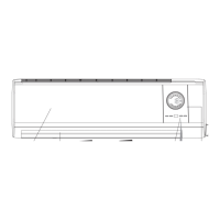
Step-by-step guide for disassembling indoor unit components like front panel, filter, and guide louver.
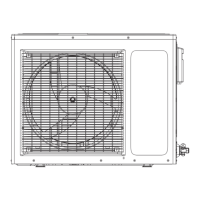
Guide for disassembling outdoor unit parts: top cover, handle, and rear side plate.
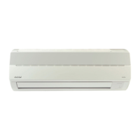
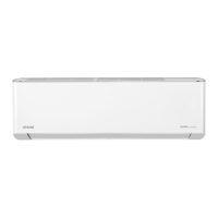
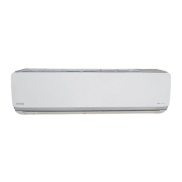
Visual representation of indoor unit components with numbered parts for identification.
Detailed list of indoor unit parts, their descriptions, part codes, and quantities.
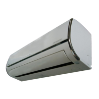
Visual representation of outdoor unit components with numbered parts for identification.
Detailed list of outdoor unit parts, their descriptions, part codes, and quantities.
Analyzes causes and processing methods for compressor discharge protection issues.
Details reasons and processing for low voltage overcurrent protection.
Addresses communication issues between units and processing methods.
Troubleshooting for sensor malfunctions like open or short circuits.
Explains causes and processing for compressor overload protection.
Covers system-level malfunctions, including overload protection.
Provides processing methods for IPM module protection errors.
Details reasons and processing for PTC protection errors.
Provides a flowchart for handling module protection issues and related checks.