Do you have a question about the Toyotomi Laser 300 and is the answer not in the manual?
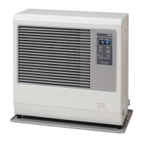
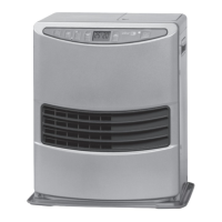
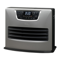
Overview of the Laser Heating System's advanced features and benefits.
Table detailing dimensions, weight, and flue pipe hole size for models.
Explanation of the heating cycle, programmable timer, and operating stages.
Lists the primary components and systems that make up the Laser Heater.
Details the heat chamber and heat exchanger, and their function in combustion.
Describes the burner's construction, igniter, fuel line, flame sensor, and burner ring.
Details the burner ring assembly design and its mounting.
Explains the burner mat's role in fuel vaporization and its part numbers.
Describes the flame rod sensor's function and mounting location.
Explains the ceramic-type igniter's purpose and part number.
Details flue pipe installation, thickness, and design for air intake/exhaust.
Describes the turbo fan for combustion, dual function fans, and 3-speed operation.
Explains the air circulation fan's role in room heating and its speeds.
Discusses external fuel tank installation requirements and options.
Details the fuel pump mounting, solenoid, and control circuit.
Explains the control circuit board's functions: safety, relays, clock, thermostat.
Describes the room temperature sensor's range, mounting, and wire extension.
Details the constant level valve's auto shutoff, reset button, and float mechanism.
Explains the use of insulating cloth covers for exhaust lines for safety.
Describes the fan filter's role in user safety and preventing physical injury.
Details fuse ratings and their function in protecting against power surges.
Explains the overheat protector switch, its rating, and reset procedure.
Describes the pressure relief plate's location and function to prevent damage.
Explains how fuel and air mix, ignite, and produce heat, with overheat protection.
Details how the venting system channels air for combustion and exhausts by-products.
Explains fuel movement from storage to burner, controlled by the fuel pump.
Refers to Section 6 for electronic diagrams like wiring and circuit board layouts.
Highlights built-in safety features protecting users and the heater.
Explains automatic heater restart after power restoration.
Describes how to resume operation within 3 seconds of power interruption.
Describes the procedure to restart reignition if it takes too long.
Explains how to view and interpret past error codes displayed by the unit.
Details the 'E-22' error code for repeated ignition failures and reset method.
Lists normal temperature ranges for burner thermistors on different models.
Explains what settings are stored in memory during power failure.
Provides information on backup time for stored data and unit lifespan.
Describes the procedure to clear the error code history.
Explains 'E-0' error for abnormal frequency and reset steps.
Details symptoms and behavior of a power button short circuit.
Explains 'E-0' error for low voltage and its detection period.
Describes behavior when flame is detected during incorrect operation.
Details the manual procedure for cleaning the igniter using button sequences.
Explains the automatic igniter cleaning cycle that runs at 2 AM.
Describes how to enter and exit manual combustion modes and view data.
Explains how to adjust settings for high altitude operation and its effects.
Details the automatic combustion cleaning cycle that occurs after 2 hours of high mode.
Explains how to adjust fuel pump flow rates across 9 levels for different modes.
Defines routine and corrective maintenance for heater performance.
Provides a schedule of periodic maintenance tasks for optimal heater operation.
Covers causes and procedures for heater efficiency losses and servicing needs.
Detailed steps for opening and cleaning the heat exchanger and burner assembly.
Procedure for draining fuel system to remove water and contaminants.
Recommends checking and cleaning the fuel filter or water block filter.
Lists error codes (Hi/Lo) related to room temperature and sensor issues.
Guides on inspecting air lines for leaks, connections, and obstructions.
Procedure to visually inspect igniter glow and check power/resistance.
Details how to disassemble and clean the fuel inlet strainer.
Explains how to replace blown fuses and the importance of correct ratings.
Guides on diagnosing and cleaning fuel contamination issues in the system.
Procedure for cleaning the exhaust fan and blower motor assembly.
Diagram illustrating the electrical components and their connections on the circuit board.
Provides reference values for resistors and capacitors in the system.
Lists expected voltage readings for various components during operation.
Details timing specifications for control board operations like motor start and preheating.
Specifies detection current and allowable leakage resistance for flame detection.
Lists temperature settings, differentials, and resistance values for the room thermistor.
Details temperature settings and resistance for flame extinguishing control.
Specifies resistance values and preheat times for reduction resistor 1.
Specifies resistance values and preheat times for reduction resistor 2.
Diagram showing how room temperature affects combustion modes (H, M, L, OFF).
Explains combustion modes based on temperature differentials after ignition.
Describes power saver logic for flame extinguishing based on temperature.
Details resistance values for detecting burner thermistor faults.
Lists frequency control values for various fuel pump combustion modes (H, M, L).
Specifies RPM ranges for blower motor speeds (High, Medium, Low) in different modes.
Lists RPM values for motor lock detection during combustion and displays 'E-8'.
Details fan motor control ratios (ON:OFF) for different speed modes.
Describes behavior when abnormal overheat is detected, showing 'E-12'.
Explains how settings are maintained during power failures.
Lists error codes (E-0, E-2, E-6, E-8, E-12, E-13, E-22, E-23) and their causes.
Comprehensive guide to diagnosing and resolving operational failures.
Troubleshooting steps for when the unit does not operate, checking fuse and ribbon cable.
Troubleshooting steps for E-8 error (motor lock/obstruction), checking room temp and fan.
Troubleshooting steps for E-2 error (igniter/flame sensor issues), checking fuel and voltage.
Troubleshooting steps for E-6 error (flue pipe blockage/leak), checking fuel pump and wiring.
Troubleshooting steps for E-22 error (ignition failure), checking fuel and main board.
Troubleshooting steps for E-12 error (overheat protector activated), checking fan cover and circulation fan.
Troubleshooting steps for E-13 error (burner thermistor), checking resistance and wiring.
Troubleshooting for ignition failure (E-2) occurring three times, checking fuel and igniter.
Troubleshooting yellow flame, noise, smoke by checking fuel pump, burner ring, and ducts.
Troubleshooting for 'LO' room temp indicator, checking room temp sensor and wiring.
Troubleshooting for E-23 error (primary flame sensor malfunction), checking sensor and wiring.
Troubleshooting for E-0 error (power source failure), checking power supply and main board.
| Ignition System | Automatic |
|---|---|
| Heating Power | 3.0 kW |
| Fuel Consumption | 0.086 - 0.313 l/h |
| Tank Capacity | 5.4 l |
| Safety Features | Tip-over protection |