Do you have a question about the Toyotomi MTN A371DV and is the answer not in the manual?
Essential safety guidelines to prevent injury and damage during operation and maintenance.
Critical warnings regarding installation, electrical safety, handling, and environmental considerations.
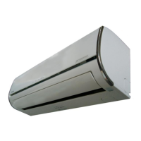
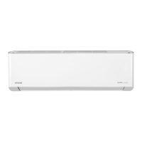
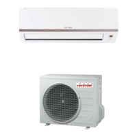
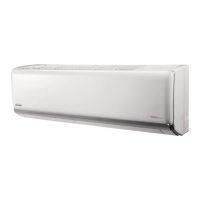
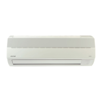
Physical dimensions and specifications for the indoor unit, including width, depth, and height.
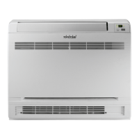
Physical dimensions and installation space requirements for the outdoor unit.
Electrical wiring schematic detailing connections for the indoor unit's components.
Electrical wiring schematic detailing connections for the outdoor unit's components.
Specifies torque values for various fasteners used during the installation process.
Guidelines for selecting appropriate power cables and ensuring secure connections.
Details on refrigerant pipe sizing, maximum permissible length, and elevation differences.
Step-by-step procedures for the initial installation, including purging and evacuation.
Procedure for safely recharging refrigerant into systems that have been in operation for extended periods.
Steps for collecting refrigerant into the outdoor unit before indoor unit servicing.
Procedures for evacuation and refrigerant charging during outdoor unit repair or re-installation.
Glossary of technical abbreviations used throughout the electronic function sections.
Explanation of icons and indicators shown on the indoor unit's display board.
Details on the unit's internal protection mechanisms, including compressor and fan safety features.
Overview of various operating modes (Cooling, Heating, Auto, etc.) and system functions.
List of error codes displayed on the indoor unit and their corresponding LED status meanings.
Step-by-step troubleshooting guides for common issues like EEPROM errors, communication failures, and sensor faults.
| Type | Split System |
|---|---|
| Power Supply | 220-240V, 50Hz |
| Refrigerant | R410A |
| Operating Temperature (Cooling) | 18°C to 43°C |
| Operating Temperature (Heating) | -7°C to 24°C |