Connection
Note:
The console port is the first port on the right of the front panel.
Please keep the device power off when you plugging the console cable.
Do not connect the console port with other ports by RJ45 cable.
After completing the installation, please verify the following items:
There are 5~10cm of clearance around the sides of the device for ventilation and
the air flow is adequate.
The voltage of the power supply meets the requirement of the input voltage of the device.
The power socket, device and rack are well grounded.
The device is correctly connected to other network devices.
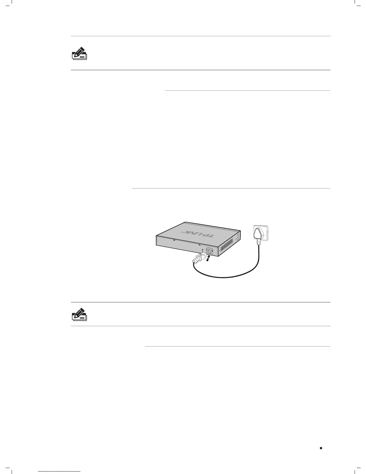
Plug in the negative connector of the provided power cord into the power socket of the
device, and the positive connector into a power outlet as the following figure shown.
Connecting to Power SupplyFigure 4-3
Note:
from the package and the socket in your situation will comply with the regulation in
After the device is powered on, it begins the Power-On Self-Test. A series of tests run
automatically to ensure the device functions properly. During this time, its LED indica-
tors will respond as follows:
The Power LED lights on all the time.
All LEDs except PWR LED flashes momentarily and then turns off.
The SYS LED flashes every second continuously, which means the initialization is finished.
 Loading...