Parallel Interface
Parallel port of POS58Ⅲ is 8-bit interface which support BUSY
handshaking. Using a D-Sub 25 pin (male) socket. Pin order of parallel port is
as follows:
Figure 1-9 Pin assignment of parallel port
The pin assignment of parallel port is shown in Table 1-2.
Pin No.
ch data. Reading occurs at
falling edge
2
3
4
5
6
7
8
9
DATA1
In
In
In
In
In
In
In
In
These signals represent the 1st bit to 8
th
bit of
the parallel data respectively. Each signal is at
HIGH level when data is logical 1 and LOW
when data is logical 0
10 /ACK
Pull up to HIGH logical level by a resistor
11 BUSY
HIGH level signal indicates th
BUSY and can not receive data
12 PE Out
HIGH level signal indicates that paper running
out.
13 SEL Out
Pull up to HIGH logical level by a resistor
15 /ERR
Pull up to HIGH logical level by a resistor
14,16,17
NC --- No connection
18-25 GND
--- Grounding Logical “0” level
Note: (1) "In" denotes input to the printer, "Out" denotes output from the printer.
(2) Signal level is TTL standard.
Table 1-2 Pin assignment of Parallel Port
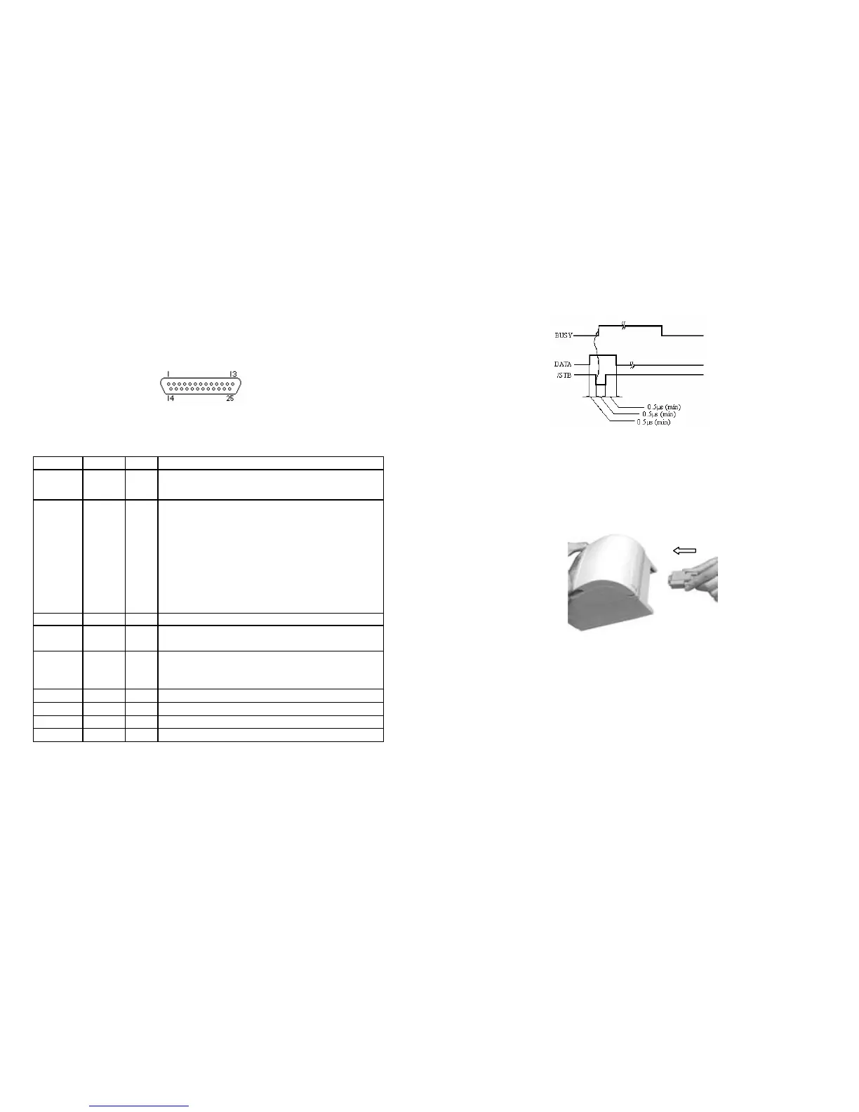
The timing chart for handshaking signals in parallel port is as follows:
6
Figure 1-10 Signal timing chart of parallel port
1. Make sure that the printer and computer is turn off. Plug the cable
connector into the printer’s interface connector as follows:
Figure 1-11 Connecting to the Parallel Interface
F Note
:
Screw down the screws on both sides of the cable connector.
2. Attach the other end of the cable to the computer.