800-448-8979
TRAC-RITE
7. SECURING THE GUIDES
7.1 Pull the door down to within 6” of the floor (See Figure
8). Adjust the door guides so there is 1/8” to 1/4” of play side
to side. If the clearance is too small the door will be hard to
operate. Too much clearance will allow the door to move
side to side excessively and may cause the door to bind.
7.2 Attach the guides to the jambs as follows:
7.2a For steel jambs, secure with supplied Tek screws, using
one fastener per mounting hole.
7.2b For wood jambs, secure with supplied lag bolts, using
one fastener per mounting hole.
7.2c For masonry jambs, install masonry clips along the
guide height, using one clip located next to each mounting
hole on the guide. Make sure the clips are flush with the
back of the guide. Attach each clip to the guide with two (2)
small (#12-14 x 3/4”) supplied Tek screws (See Figure 8).
Drill a hole in the masonry and fasten the clip in place using
supplied anchors.
WARNING
!
Immediately install keepers and door stops. These
devices will prevent the door from rolling up out of the
guides and possibly causing injury.
!
CAUTION
Excessive force in operation may cause damage to
the door. If the door binds, adjust guides to allow
appropriate movement.
Figure 7
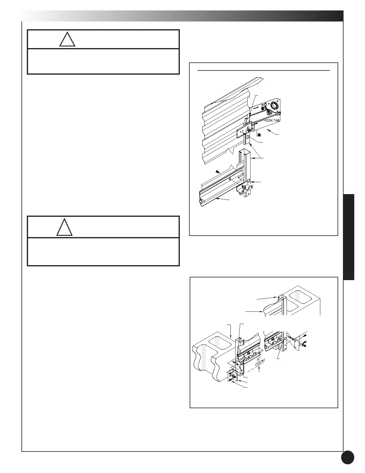
6. KEEPER AND TOP STOP ASSEMBLY
6.1 Remove whiz nut from each side of door bottom bar
(See Figure 7).
6.2 Attach one keeper to the bottom interior edge of each
side of the door with one (1) 1/4” carriage bolt and whiz nut
that was just removed. On doors with two handles, install
one of the handles as you install the left side keeper (See
Figure 10).
6.3 Tighten whiz nuts to fasten keepers.
6.4 Slide the stops up into position so that the hook tab
mates with the upper hole on the stop (See Figure 7). Fasten
each door stop to each bracket as shown using one (1) 5/16”
track bolt and nut through the lower hole of the stop.
6
BENT CURTAIN LEAD IN
DOOR BRACKET
DOOR STOP
5/16” TRACK BOLT & NUT
DOOR GUIDE
KEEPER
1/4” CARRIAGE BOLT & NUT
BOTTOM OF
DOOR CURTAIN
DOOR AXLE ASSEMBLY NOT SHOWN FOR CLARITY
Figure 8
NON-MASONRY
FASTENING HOLES
MASONRY ANCHOR
MASONRY CLIP
TEK SCREWS #12-14 x 3/4”
MAINTAIN 1/8 TO 1/4” GAP (3-6MM)
BETWEEN GUIDE AND WEAR GUARD
DOOR CURTAIN
DOOR GUIDE
BLOCK JAMB
944_Manual_522000revH_818 color.indd 7 9/10/2018 1:36:46 PM
 Loading...