www
.
T
r
a
il
F
X
.
c
om
Page 3 of 8 Rev 051918
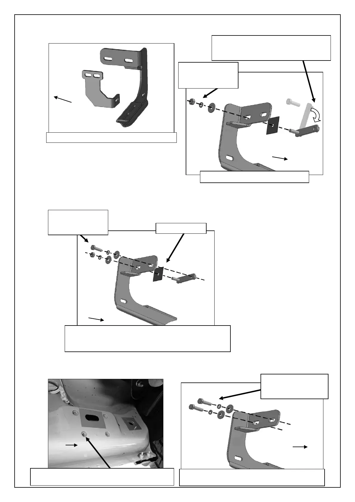
b. Select the driver side front Mounting Bracket, (Figure 6). Attach the Bracket to the threaded end of the Bolt Plate with (1)
8mm Flat Washer, (1) 8mm Lock Washer and (1) 8mm Hex Nut, (Figure 7A). Do not tighten at this time.
c. Remove the 8mm Hex Bolt from the nut on the Bolt Plate from Step 3a. Rotate the Bolt on the Bolt Plate until the threaded
nut lines up with the remaining hole in the Mounting Bracket and body panel, (Figure 7B). Attach the Bracket to the
threaded Nut Plate with (1) 8mm x 30mm Hex Bolt, (1) 8mm Lock Washer and (1) 8mm Flat Washer. Do not tighten
hardware at this time.
Models with factory threaded inserts:
a. Attach the driver side Front Bracket to the threaded inserts with (2) 8mm x 30mm Hex Bolts, (2) 8mm Lock Washers and
(2) 8mm Flat Washer, (Figures 8 & 9). Leave hardware loose.
(Fig 6) Driver side front and center Brackets
Remove Hex Bolt, rotate Bolt/Nut Plate
to line up threaded nut with body panel
and Mounting Bracket (see arrow)
8mm Lock Washer
(Fig 7A) Attach Bracket to Bolt Plate
(Fig 9) Driver side front models with factory
installed threaded inserts. Bolt Plate not required
(2) 8mm Lock Washers
(Fig 8) Driver side front mid 2015-on, an example
of models with factory installed threaded inserts
(Fig 7B) Attach Bracket to threaded end of Bolt Plate
first. Remove 8mm Hex Bolt (see Fig 3). Rotate Bolt
Plate to line up with remaining factory hex shaped hole.
8mm Lock Washer
 Loading...