Do you have a question about the Tranberg TEF 4900 and is the answer not in the manual?
Overview of the 4900 Commander control system, its purpose, and design principles.
Introduces the TEF 4900 Commander system components and their interconnection via RS-485.
Illustrates the generic system architecture with a diagram showing panels, Master CPU, and output modules.
Details system capabilities, application areas, communication methods, and key features.
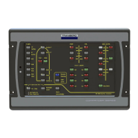
Explains panel button and LED functionality, states, and configuration options.
Details the Master CPU's inputs, outputs, power supply, and LED indicator functions.
Information on the VDR gateway module for sending system status to a Voyage Data Recorder.
Details on the SCADA gateway module for remote control and alarm silence messages.
Configuration of panel address, column settings, and legal remote control commands.
Overview of panel connectivity, button functions, and hardware components like CPU and RS-485 circuitry.
Explains panel buttons, LEDs, their states, and testing procedures for visual indicators.
Covers communication error indications, panel address/column settings, and non-volatile memory functions.
Procedures for clearing panel data, retention time, and physical connections for power and network.
Overview of available output modules, part numbers, voltage, monitoring, and common hardware.
Details on capacity, current sensing, and manual operation of relay output modules.
Information on analog output modules, their operations, and current supervision features.
Details on power connections, fuses, RS-485 network, and LEDs for output modules.
Introduction to system installation, component placement, and general connection diagrams.
Guidelines for connecting power and communication cables to modules and panels.
Explanation of main power supplies and procedures for correct system termination.
Procedures for terminating outputs and applying power for the first time.
Steps for testing the system, troubleshooting failures, and module replacement procedures.
Information regarding type approval by DNV-GL for the system.
Contact information for technical clarifications and company details.
| Brand | Tranberg |
|---|---|
| Model | TEF 4900 |
| Category | Control Systems |
| Language | English |