Copyright © 2005 – 2021 R. STAHL TRANBERG AS. All rights reserved. Page 8 of 38
Manual or automatic changeover to spare outputs
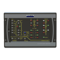
Text and graphics on panel
The panels have backlight with manual dimming functionality. The text and graphics are
laser engraved, providing the users with clear and precise information, readable in
daylight as well as in the dark.
The construction consists of a machined, black aluminum frame with a recessed button
surface made of Lexan. The Lexan film is painted on the reverse side as well as laser
engraved on the same side. This ensures a very durable front.
Button quantity and panel size
The panels come in five different lengths, depending on the number of buttons. All
panels have the same height.
The buttons are injection molded in black color. A Lexan film in various colors is
inserted in a recess on top of the button. All button switch elements are of the metallic
dome type.
Button placement
Buttons are placed in a grid with 8 positions vertically and from 3 to 8 horizontally.
Buttons may be left out for clarity. This has no impact on software or any other settings.
Button functionality
Each button has two LEDs: One green and one red. Via software commands, these may
light up in a number of combinations: Off, steady on or flashing.
A single press on a button may have several functions, depending on the on the
configuration, button status, and the time the button has been pressed (short / long).
In general, there are four ‘normal’ states of a button:
Off. No LEDs will light up.
Rapid green flash: The panel awaits a confirmation from the output module that
the corresponding output has turned on.
Continuous green: The output module has confirmed that the corresponding
output has been turned on.
Slow green flash: The corresponding spare output has been turned on and is
confirmed.
Failure combinations include:
Flashing red and green: The output channel (relay) reports a malfunction
(broken fuse or lamp) on the main output (e.g. main lantern). The buzzer will
sound. This is an unacknowledged alarm. When pressed at this stage, the
button will flash green and the spare output will be switched on.


 To Next Page