18-HE58D1-5 11
Installer’s Guide
MEASURING AIR FLOW
1. Equipment Required
-
A magnahelic guage or other device capable of mear-
suring 0 to 1.0 in. water of differential pressure.
2 pieces of natural rubber latex tubing, 1/8" ID, 1/16"
wall works best.
NOTE: Be sure to remove cap from pressure port
before inserting tubing. Insure tubing is well seated
in pressure ports.
NOTE: The tubing should extend in the pressure
port approximately 1 inch.
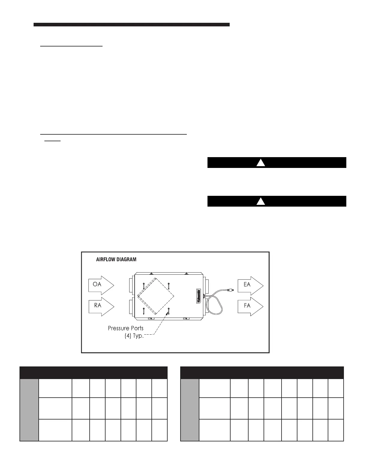
2. Cross Core Static Pressure Measurement Instruc-
tions
- The individual differential static pressures
(DP) are measured using the installed pressure ports
located in the front of the units core access doors.
NOTE: These ports are carefully located on the unit
to give the most accurate airflow measurement.
Do not relocate pressure ports.
To read SCFM of Fresh Air (FA) install the "high"
pressure side (+) of your measuring device to the
Outside Air (OA) port and the "low" pressure side (-)
to the Fresh Air (FA) port.
To read SCFM of Room Air (RA) install the "high"
pressure side (+) of your measuring device to the
Room Air (RA) port and the "low" pressure side (-) to
the Exhaust Air (EA) port.
If guage drops below zero, reverse tubing connec-
tions.
Use the reading displayed on your measurement
device to cross reference the CFM output using the
conversion chart
NOTE: Be sure to replace cap into pressure port
when airflow measuring is completed.
NOTE: For best performance the airflow rate for
both the Fresh Air and the Exhaust Air should
be roughly equal ("balanced"). In some facilities a
slight positive or negative pressure in the building
is desired. Envirowise energy recovery ventilators
can generally operate with a flow imbalance of up
to 20% without significant loss in energy recovery
efficiency.
Make sure clean filters are installed before balanc-
ing air flow. Dirty or clogged filters reduce airflow
through the unit.
The proper airflow range for the models are:
EERVR100A1P00BA: 50-140 CFM
EERVR200A1P00BA: 100-200 CFM
EERVR300A1P00BA: 150-300 CFM
Differential Static Across Core DSP vs. CFM
EERVR100
DSP 0.10 0.20 0.30 0.40 0.50
Fresh Air
(FA)
CFM 28 57 85 113 142
Room Air
(RA)
CFM 28 57 85 113 142
Differential Static Across Core DSP vs. CFM
EERVR200
EERVR300
DSP 0.10 0.20 0.30 0.40 0.50 0.60
Fresh Air
(FA)
CFM 59 119+ 178 238 297 356
Room Air
(RA)
CFM 59 119+ 178 238 297 356
 Loading...