12 18-AC98D1-7D-EN
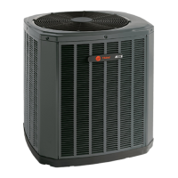
With Variable Speed S-Series Furnace
NOTES:
1) For PWM (BK) enabled thermostats, cut the BK jumper on
the IFC and connect wiring.
2) The factory Y1-O jumper must remain in place for proper
LED read out in cooling mode.
3) Y1 and Y2 wiring from the thermostat must connect to
the IFC for proper airflow and LED readout.
4) Single compressor and two compressor airflow is auto-
matically set with the IFC Menu options in ODU section.
2-1=2 stage / 1 compressor (1st stage airflow = 75%)
2-2=2 stage / 2 compressors (1st stage airflow = 50%)
Furnace
Y1Y1
Thermostat
Outdoor
Unit
R
G
W1
W2
R
G
B/C B/C B
Y1
W1
W2
Y2Y2Y2
24 VAC HOT
FAN
SOV
24 VAC
Common
HEATING
OO
BK
BK
(1)
(2)
COOL
1st STAGE
COOL
2nd STAGE
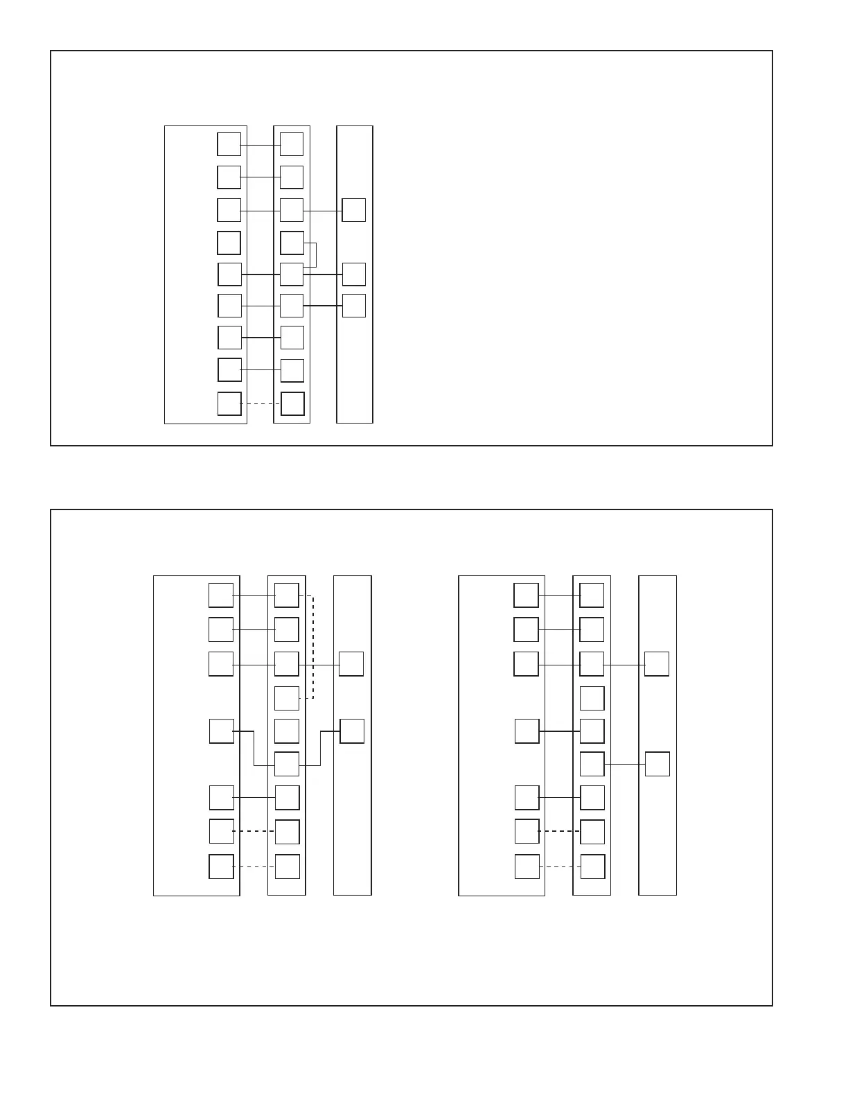
With TEM 3, 4, 6, 8With TAM 4, 7, 9
• Units with pigtails require wirenuts for connections. Cap all unused wires.
•
In AC systems for multiple stages of electric heat, jumper W1 and W2 together if comfort control has only one stage of heat.
TEM3/4 - Bypass air handler and connect Y from comfort control directly to OD unit
y
** TEM6 only - When using a BK enabled comfort control, cut BK jumper and bypass Y1 and Y2 at the air handle
r. Connect BK from comfort
control to BK of the air handle
r
TAM4 only - Wire as shown, no BK is available
TAM7 only - When using a BK enabled comfort control, cut BK jumper on the AFC and connect BK from comfort control to BK of the air handler
Thermostat Air Handler
Outdoor
Unit
R
G
B
W1
W2
B
Y
R
G
B/C
Y
W1
W2
Blue
24 VAC HOT
FAN
24 VAC
Common
SOV
COOL/HEAT
1st STAGE
HEATING
2nd STAGE
EMERGENCY
HEAT
Pink
White
O
Y1
Y2
*
BK
WH/BLK
BK
WH/BLK
Thermostat Air Handler
Outdoor
Unit
R
G
B
W1
W2
B
R
G
B/C
Y
l
W1
W2
Blue
24 VAC HOT
FAN
24 VAC
Common
SOV
COOL/HEAT
1st STAGE
HEATING
2nd STAGE
EMERGENCY
HEAT
Pink
White
O
Y
l
Y
O
Y
O
BK
WH/BLK
BK
WH/BLK
**
For 018J - 060J, 060K, and 061C Models:
 Loading...