Do you have a question about the Trane 4TTR5060N and is the answer not in the manual?
Essential safety warnings and precautions for handling the equipment and refrigerant.
Step-by-step instructions for preparing and brazing refrigerant lines.
Completing brazing, handling heat damage, and installing the filter drier correctly.
Steps for pressurizing lines with nitrogen and checking for leaks using a soapy solution.
Procedure for evacuating the system to a specific micron level for moisture removal.
Instructions for safely opening the gas service valve after leak checks.
Procedure for opening the liquid service valve with critical safety warnings.
Steps to ensure previous sections are completed and thermostat is set correctly.
Steps for applying power, waiting for crankcase heat, and turning the thermostat on.
Detailed steps and charts for adjusting system charge using subcooling.
Procedure for calculating and applying refrigerant charge based on line length.
A comprehensive checklist for final system inspection and operational verification.
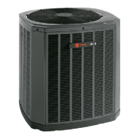
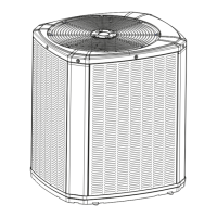
This document is an Installation and Operation Manual for Trane Condensing Units, specifically models 4TTR5018 through 4TTR5060. It provides comprehensive instructions for the proper installation, startup, and maintenance of these outdoor condensing units, emphasizing compliance with national, state, and local codes. The manual is intended for individuals with adequate electrical and mechanical experience, as any attempt to repair the product without proper knowledge could result in personal injury or property damage.
The Trane Condensing Units are designed to be part of a central air conditioning system, working in conjunction with an indoor evaporator coil and air handler to provide cooling. These units utilize R-410A refrigerant, which operates at higher pressures than older refrigerants like R-22. The primary function of the condensing unit is to compress and condense the refrigerant, releasing heat to the outdoor environment, thereby facilitating the cooling cycle within the building. The manual stresses the importance of installing only approved matched indoor and outdoor systems to ensure maximum efficiency, optimum performance, and overall system reliability.
The manual outlines several key considerations for the proper usage and installation of these condensing units. Unit location is critical, with recommendations for unrestricted top discharge areas (at least five feet clearance), three feet clearance in front of control boxes and other service-requiring sides, and a minimum of 12 inches from any wall or surrounding shrubbery to ensure adequate airflow. It also advises against locating units near bedrooms due to potential operational sounds and away from structures where roof runoff water could pour directly onto the unit. For installations within one mile of salt water, the addition of a Seacoast Kit (BAYSEAC001) is recommended.
Refrigerant piping limits are specified, with a maximum total line length of 150 feet (including lift) and a maximum vertical change of 50 feet. The manual provides detailed instructions for preparing the unit, including checking for damage upon arrival and removing the unit from its pallet by cutting securing tabs.
For electrical connections, the manual differentiates between low voltage and high voltage wiring. It provides hook-up diagrams for various indoor unit configurations (TEM 3, 4, 6, 8, TAM 4, 7, 9, and furnace systems) and specifies maximum wire lengths for different AWG sizes to ensure proper low voltage operation. For high voltage, it mandates compliance with the equipment nameplate and all national, state, and local codes, recommending a separate disconnect switch at the outdoor unit and flexible electrical conduit to minimize vibration transmission. Proper grounding of the outdoor unit is also emphasized.
The startup procedure includes ensuring all installation steps are completed, setting the system thermostat to OFF, applying power to the units, and waiting one hour before starting if a compressor crankcase heater accessory is used and the outdoor ambient temperature is below 70°F.
The manual details critical maintenance-related procedures, particularly concerning refrigerant handling and system charging. It highlights that R-410A systems use POE oil, which readily absorbs moisture, necessitating that the system remain sealed whenever possible. If a system has been open to the atmosphere for more than four hours, the compressor oil must be replaced. It also warns against breaking a vacuum with air and always recommends changing driers when opening the system for component replacement.
Brazing of refrigerant lines is covered extensively, including deburring pipe ends, cleaning surfaces, purging with dry nitrogen to prevent oxidation, and wrapping valve bodies with wet rags to avoid heat damage. A crucial step is the refrigerant line leak check, where lines and the evaporator coil are pressurized to 150 PSIG with dry nitrogen, and all brazed locations are checked for leaks using a soapy solution. Any leaks must be repaired before proceeding.
Evacuation of the refrigerant lines and indoor coil is required until a micron gauge reads no higher than 350 microns, followed by observing the gauge to ensure it does not rise above 500 microns in one minute. The manual provides specific instructions for opening the gas and liquid service valves, emphasizing extreme caution when opening the liquid line service valve to prevent abrupt release of system charge.
System charge adjustment is a key maintenance feature, with subcooling (in cooling mode) being the recommended method for charging above 55°F ambient outdoor temperature for TXV/EEV systems. For fixed orifice systems, superheat charging is used. The manual provides detailed charts and steps for determining the correct subcooling or superheat values based on line length, lift, and indoor/outdoor temperatures. It also includes a "Weigh-In Method" for initial installations or when power is unavailable, or temperatures are outside the range for standard charging methods. The process involves measuring liquid line temperature and pressure, and then using a charging chart to determine if refrigerant needs to be added or recovered.
Finally, the manual includes a "Checkout Procedure" checklist to ensure proper operational performance after installation, including verifying leak-free refrigerant lines, proper insulation, secure and isolated lines, sealed masonry passages, tight electrical connections, smooth outdoor fan operation, free-draining indoor coil, unobstructed registers and grilles, installed return air filter, correct airflow setting, and safe operation in all modes. Pressure curves are provided at the end of the document to help verify typical performance. The document explicitly states that it is customer property and should remain with the unit, to be returned to the service information pack upon completion of work.
| Brand | Trane |
|---|---|
| Model Number | 4TTR5060N |
| Category | Heat Pump |
| Nominal Capacity (tons) | 5 |
| Cooling Capacity (BTU/h) | 60000 |
| Heating Capacity (BTU/h) | 60000 |
| SEER Rating | 16 |
| Refrigerant | R-410A |
| Voltage | 208/230 |
| Phase | 1 |