Do you have a question about the Trane 4TTR7 Series and is the answer not in the manual?
Emphasizes installer background and general safety practices.
Covers R-410A, pressure, liquid line valve, and POE oil.
Focuses on hazards of working with live electrical components.
Addresses specific component risks like hot compressor domes.
Specifies maximum total and vertical refrigerant line lengths.
Covers clearance, noise, airflow, and condensation avoidance.
Addresses snow accumulation and unit elevation.
Details requirements for saltwater environments.
Steps for checking damage and removing from pallet.
Requirements for concrete slabs and leveling.
Details standard and alternate line/valve sizes.
Explains initial charge and verification methods.
Instructions for determining line length and vertical change.
Importance and method of insulating lines.
Precautions for retrofit installations.
Guidance on minimizing noise and proper support.
Detailed steps for brazing refrigerant lines.
Steps for pressurizing and checking for leaks.
Steps for achieving system vacuum.
Procedure for opening the gas service valve.
Procedure and safety warning for liquid valve.
Table specifying maximum wire lengths.
Wiring diagrams for different control systems.
Safety and code compliance for power supply.
Installation of disconnect and grounding.
Step-by-step guide to initiating system operation.
Guidelines for measuring temps for subcooling/weigh-in.
Method for charging in warmer conditions.
Method for charging in cooler conditions using weight.
Checklist for final system verification.
Table of common faults and their causes.
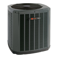
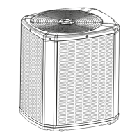
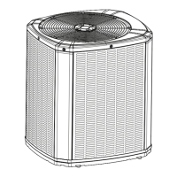
This document is an installer's guide for Trane Condensing Units, specifically models 4TTR7024A, 4TTR7036A, 4TTR7048A, and 4TTR7060A. It provides comprehensive instructions for the safe and proper installation, start-up, and maintenance of these outdoor air conditioning units. The guide emphasizes safety, proper handling of refrigerants, and electrical procedures to ensure optimal performance and longevity of the equipment.
The Trane Condensing Units (4TTR7 series) are outdoor components of a central air conditioning system. Their primary function is to condense refrigerant gas into liquid, releasing heat to the outdoor environment. This process is crucial for cooling indoor spaces when paired with an indoor evaporator coil and air handler. These units are designed to operate with R-410A refrigerant, a high-pressure refrigerant that requires specific handling procedures and approved service equipment. The guide details the steps for connecting the outdoor unit to the indoor unit via refrigerant lines, ensuring a sealed and properly charged system. It also covers the electrical connections necessary for the unit's operation, including low voltage wiring for thermostat control and high voltage power supply.
The installation process for these condensing units involves several key stages, each with specific usage features and considerations:
The installer's guide also touches upon aspects that contribute to the long-term maintenance and proper functioning of the unit:
By following these detailed instructions, installers can ensure that the Trane Condensing Units are installed, started up, and maintained to deliver reliable and efficient cooling performance.
| Refrigerant | R-410A |
|---|---|
| Sound Level | As low as 72 dB |
| Cooling Capacity (BTU/h) | 18, 000 - 60, 000 |
| Heating Capacity (BTU/h) | 18, 000 - 60, 000 |
| Type | Heat Pump |
| Warranty | 10 Year Limited Warranty on compressor, 10 Year Limited Warranty on outdoor coil |
| Stages | Single Stage |