6 18-AC94D1-4C-EN
5.2 Factory Charge
The outdoor condensing units are factory charged with the system charge required for the outdoor condensing
unit, ten (10) feet of tested connecting line, and the smallest rated indoor evaporative coil match. Always verify
proper system charge via subcooling (TXV/EEV) or superheat (fixed orifice) per the unit nameplate.
Section 5. Refrigerant Line Considerations
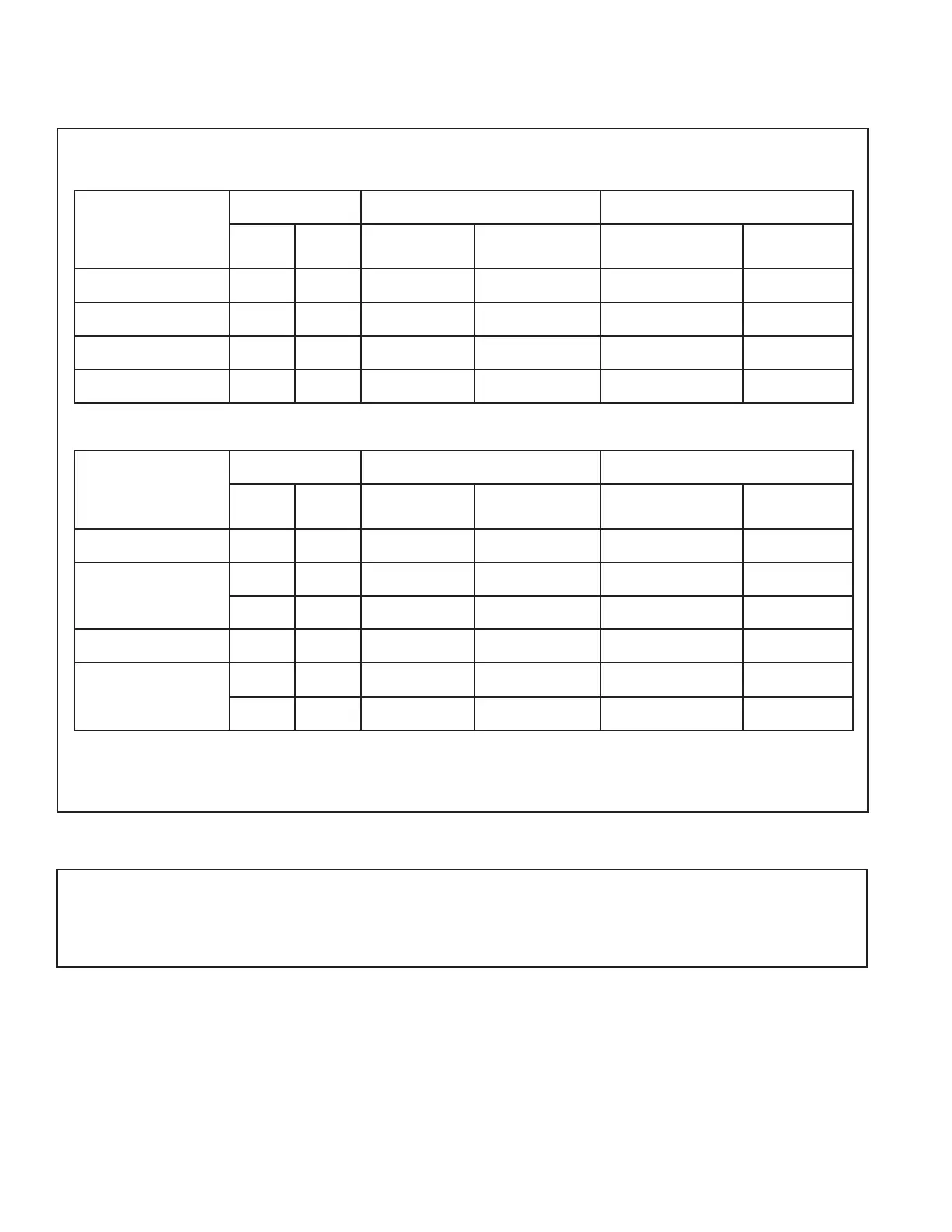
5.1 Refrigerant Line and Service Valve Connection Sizes
Table 5.1
RATED
LINE SIZES
Line Sizes Service Valve Connection Sizes Max Line & Lift Lengths
Vapor
Line
Liquid
Line
Vapor Line
Connection
Liquid Line
Connection
TOTAL Max
Line Length (ft.)
Max Lift (ft.)
4TTR7024A
3/4
3/8 3/4 3/8 150 50
4TTR7036A
3/4
3/8 3/4 3/8 150 50
4TTR7048A
7/8
3/8 7/8 3/8 150 50
4TTR7060A
1-1/8
3/8 7/8 3/8 150 50
ALTERNATE
LINE SIZES
Line Sizes Service Valve Connection Sizes Max Line & Lift Lengths
Vapor
Line
Liquid
Line
Vapor Line
Connection
Liquid Line
Connection
TOTAL Max
Line Length (ft.)
Max Lift (ft.)
4TTR7024A
3/4
3/8 3/4 3/8 150 50
4TTR7036A
5/8
3/8 3/4 3/8 150 50
7/8
3/8 3/4 3/8 150 50
4TTR7048A
3/4
3/8 7/8 3/8 150 50
4TTR7060A
3/4
3/8 7/8 3/8 150 50
7/8
3/8 7/8 3/8 150 50
Note: For other line lengths, Refer to Refrigerant Piping Application Guide, SS-APG006-EN or Refrigerant Piping
Software Program, 32-3312-xx (latest revision).
 Loading...