EasyManua.ls Logo

Trane 4TTR4042N - User Manual

Trane 4TTR4042N
22 pages
Print Icon
To Next Page IconTo Next Page
Loading...
18-AC51D1-10F-EN
ALL phases of this installation must comply with NATIONAL, STATE AND LOCAL CODES
IMPORTANT – This Document is customer property and is to remain with this unit. Please return to service informa-
tion pack upon completion of work.
Condensing Units
These instructions do not cover all variations in systems or provide for every possible contingency to be met in connection with
the installation. Should further information be desired or should particular problems arise which are not covered sufficiently for the
purchaser’s purposes, the matter should be referred to your installing dealer or local distributor.
Note: The manufacturer recommends installing only approved matched indoor and outdoor systems. Some of the benefits of
installing approved matched indoor and outdoor split systems are maximum efficiency, optimum performance and the best overall
system reliability.
4TTR4018 – 060
Table of Contents
Section 1. Safety ..................................................................................... 2
Section 2. Unit Location Considerations ............................................. 3
Section 3. Unit Preparation.................................................................... 4
Section 4. Setting the Unit ..................................................................... 4
Section 5. Refrigerant Line Considerations ......................................... 4
Section 6. Refrigerant Line Routing ..................................................... 5
Section 7. Refrigerant Line Brazing ...................................................... 7
Section 8. Refrigerant Line Leak Check ............................................... 7
Section 9. Evacuation ............................................................................ 8
Section 10. Service Valves .................................................................... 8
Section 11. Electrical - Low Voltage ..................................................... 9
Section 12. Electrical - High Voltage .................................................. 10
Section 13. Start Up.............................................................................. 11
Section 14. System Charge Adjustment............................................. 11
Section 15. Checkout Procedures ...................................................... 15
Section 16. Refrigerant Circuits (Reference only) ............................. 15
Section 17. Wiring Diagrams ............................................................... 16
Section 18. Pressure Curves ............................................................... 20
Installation and Operation Manual
Question and Answer IconNeed help?

Do you have a question about the Trane 4TTR4042N and is the answer not in the manual?

Summary

Safety

General User Qualifications

Manual intended for individuals with electrical and mechanical experience.

Live Electrical Component Safety

Risk of death or serious injury from live electrical components during servicing.

R-410 A Refrigerant Handling

R-410A operates at higher pressures; use approved service equipment.

Liquid Line Service Valve Caution

Extreme caution when opening liquid line service valve to prevent abrupt charge release.

Refrigerant Line Considerations

Refrigerant Line Brazing

Braze The Refrigerant Lines

Step-by-step instructions for brazing refrigerant lines with nitrogen purge.

Refrigerant Line Leak Check

Check For Leaks

Procedure for leak checking refrigerant lines using nitrogen pressure and soapy solution.

Evacuation

Evacuate Refrigerant Lines and Indoor Coil

Steps to evacuate the system to a specific micron level for moisture removal.

Service Valves

Open the Liquid Service Valve

Cautions and steps for opening the liquid service valve safely.

Start Up

System Charge Adjustment

Temperature Measurements for Charging

How to measure temperatures for subcooling and superheat charging methods.

Subcooling Charging in Cooling

Procedure for subcooling charging method for outdoor temperatures above 55°F.

Subcooling Charging Chart Corrections

Charts for determining subcooling correction values based on line length and lift.

Stabilize and Measure System Parameters

Steps to stabilize the system and measure liquid line temperature and pressure.

Determine Proper Liquid Gage Pressure

Using charging chart (Table 14.2) to find correct liquid gauge pressure.

Adjust Refrigerant Level

Steps to add or recover refrigerant to match chart values.

Checkout Procedures

Pressure Curves

Overview

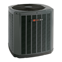
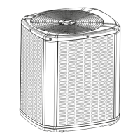
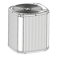
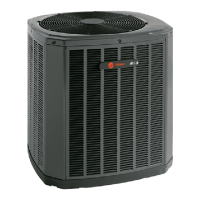
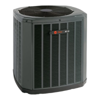
This document is an Installation and Operation Manual for Trane Condensing Units, specifically models 4TTR4018 - 060. It provides comprehensive instructions for the proper installation, operation, and maintenance of these outdoor units, emphasizing compliance with national, state, and local codes.

Function Description:

The Trane Condensing Units are outdoor components of a split air conditioning system, designed to work in conjunction with an indoor evaporator coil and air handler to provide cooling for commercial and residential applications. They utilize R-410A refrigerant and are engineered for energy-efficient indoor environments. The manual guides installers through every step from unit preparation and placement to refrigerant line installation, electrical connections, system startup, and charge adjustment, ensuring optimal performance and reliability.

Important Technical Specifications:

The manual details various technical specifications crucial for installation and operation:

  • Refrigerant Type: R-410A, which operates at 50-70% higher pressures than R-22.
  • Oil Type: POE oil, which readily absorbs moisture.
  • Unit Dimensions and Weight (Table 2.1):
    • 4TTR4018N: 29 x 26 x 29 inches, 133 lbs
    • 4TTR4019N: 29 x 30 x 33 inches, 161 lbs
    • 4TTR4024N: 29 x 26 x 29 inches, 133 lbs
    • 4TTR4025N: 29 x 30 x 33 inches, 162 lbs
    • 4TTR4030N: 33 x 30 x 33 inches, 156 lbs
    • 4TTR4036N: 33 x 30 x 33 inches, 156 lbs
    • 4TTR4042N: 37 x 34 x 37 inches, 212 lbs
    • 4TTR4048N: 29 x 34 x 37 inches, 189 lbs
    • 4TTR4049N: 45 x 34 x 37 inches, 256 lbs
    • 4TTR4060N: 45 x 34 x 37 inches, 277 lbs
  • Refrigerant Piping Limits:
    • Maximum line length: 60 feet (for lengths > 60 ft, refer to specific application guides).
    • Maximum vertical change: 60 feet.
  • Service Valve Connection Sizes (Table 5.1):
    • Models 4TTR4018N to 4TTR4036N: Vapor Line 3/4", Liquid Line 3/8".
    • Model 4TTR4042N: Vapor Line 7/8", Liquid Line 3/8" (Vapor Line Connection 3/4").
    • Models 4TTR4048N, 4TTR4049N: Vapor Line 7/8", Liquid Line 3/8".
    • Model 4TTR4060N: Vapor Line 1-1/8", Liquid Line 3/8" (Vapor Line Connection 7/8").
  • Factory Charge: Units are factory-charged for the outdoor unit, 10 feet of connecting line, and the smallest rated indoor evaporative coil match.
  • Refrigerant Adders (Table 5.2): Specifies additional refrigerant needed for line lengths beyond 10 feet. For example, for a 3/4" suction line and 3/8" liquid line, 3 oz for 20 ft, up to 27 oz for 60 ft.
  • Low Voltage Wiring (Table 11.1):
    • 18 AWG: 150 Ft. Max.
    • 16 AWG: 225 Ft. Max.
    • 14 AWG: 300 Ft. Max.
  • Charging Method: Subcooling (for TXV/EEV systems) or Superheat (for fixed orifice systems) depending on the indoor coil type. Subcooling is recommended for cooling mode when outdoor ambient is above 55°F.
  • Pressure Curves: Provided for various models (4TTR4018N, 4TTR4019N, 4TTR4024N, 4TTR4025N, 4TTR4030N, 4TTR4036N, 4TTR4042N, 4TTR4048N, 4TTR4049N, 4TTR4060N) to verify cooling performance based on outdoor temperature and indoor wet bulb temperature.

Usage Features:

  • Installation Flexibility: The units can be mounted on a support pad (concrete slab) or a roof, with considerations for structural support and sound/vibration isolation.
  • Location Guidelines: Provides recommendations for optimal placement, including minimum clearances (5 ft above, 3 ft in front of control box, 12 inches from walls/shrubbery) to ensure adequate airflow and prevent operational sounds from being objectionable. Avoid direct roof runoff water.
  • Refrigerant Line Routing: Emphasizes precautions to prevent noise and vibration transmission, recommending isolation hangers and minimizing 90-degree turns.
  • Electrical Connections: Detailed low and high voltage hook-up diagrams for various indoor unit types (TEM 3, 4, 6, 8; TAM 4, 7, 9; Furnace; Variable Speed Furnace). Requires a separate disconnect switch at the outdoor unit and grounding per local codes.
  • System Start-Up: A step-by-step process for initial system activation, including setting the thermostat, applying power, and allowing time for the compressor crankcase heater (if used) to warm up.
  • Charge Adjustment: Comprehensive instructions for accurately charging the system using either subcooling or superheat methods, including charts and tables for corrections based on line length and lift.

Maintenance Features:

  • Leak Check: Instructions for pressurizing refrigerant lines with dry nitrogen and checking for leaks using a soapy solution.
  • Evacuation: Detailed procedure for evacuating refrigerant lines and the indoor coil to a specified micron level to ensure a dry and leak-free system.
  • Service Valve Operation: Clear steps for opening both gas and liquid service valves, including warnings about the abrupt release of system charge if the liquid line valve is not opened correctly.
  • Drier Installation: For units shipped with a field-installed external drier, instructions to check the directional flow arrow and braze it into the liquid line.
  • Component Replacement: Advises changing driers when opening the system for component replacement and replacing compressor oil if the system has been open to the atmosphere for more than 4 hours.
  • Checkout Procedures: A checklist for verifying proper installation and operation, including checking refrigerant lines, insulation, drain lines, airflow, and overall system function in each mode.
  • Wiring Diagrams: Provided for troubleshooting and ensuring correct electrical connections.
  • Safety Warnings: Numerous warnings throughout the manual highlight the importance of proper handling of R-410A refrigerant, electrical components, and service valves to prevent personal injury, property damage, and equipment damage. It also includes a California Proposition 65 warning regarding chemical exposure.

Trane 4TTR4042N Specifications

General IconGeneral
Model4TTR4042N
TypeHeat Pump
SEER RatingUp to 14.5
HSPF RatingUp to 8.2
RefrigerantR-410A
Voltage208/230V
Cooling Capacity42, 000 BTU/h
Compressor TypeScroll
Electrical PhaseSingle Phase
Heating Capacity42, 000 BTU/h

Related product manuals