Do you have a question about the Trane 4TTR5018-060 and is the answer not in the manual?
Important warnings for users regarding experience, interpretation of information, and proper appliance use.
Hazards associated with live electrical components, high-pressure refrigerants, and chemical exposure.
Details on unit dimensions, weight, and recommended placement for optimal performance and reliability.
Guidelines for refrigerant line length and vertical change limitations.
Recommendations for placing the outdoor unit for best reliability and airflow.
Procedures for preparing the unit and requirements for installing a support pad.
Specifications for refrigerant line and service valve connection sizes.
Information about the factory-set refrigerant charge for the unit.
Required refrigerant line length and importance of vapor line insulation.
Precautions for using existing refrigerant lines in retrofit applications.
Guidelines for routing lines to prevent noise and ensure proper installation.
Step-by-step instructions for brazing refrigerant lines to service valves.
Method for checking refrigerant lines for leaks using dry nitrogen.
Procedure for evacuating refrigerant lines and indoor coil to the required vacuum level.
Step-by-step instructions for safely opening gas and liquid service valves.
Maximum total length of low voltage wiring based on wire size.
Diagrams illustrating low voltage wiring connections for various thermostats and air handlers.
Requirements for high voltage power supply, disconnect switch, and grounding.
Steps to follow for starting up the HVAC system after installation.
Measuring outdoor and indoor temperatures for accurate system charging.
Procedure for adjusting system charge using subcooling based on line length and lift.
Alternative method for calculating and adding refrigerant charge.
Checklist for verifying proper installation and system operation.
Schematic illustrating the refrigerant flow through the system components.
Electrical schematic for Trane condensing unit models 018N through 048N.
Electrical schematic for Trane condensing unit model 060N.
Charts showing liquid and suction pressures relative to outdoor temperature for models 018N through 048N.
Charts showing liquid and suction pressures relative to outdoor temperature for model 060N.
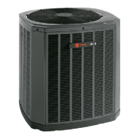
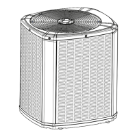
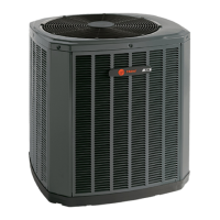
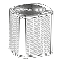
This document is an installation and operation manual for Trane Condensing Units, specifically models 4TTR5018 through 4TTR5060. It provides comprehensive instructions for the proper installation, startup, and maintenance of these units, emphasizing compliance with national, state, and local codes. The manual is intended for individuals with adequate electrical and mechanical experience, highlighting safety precautions and best practices throughout the process.
The Trane Condensing Units are designed to be a core component of a central air conditioning system. They work in conjunction with an indoor evaporator coil and refrigerant lines to provide cooling for residential and commercial applications. These units utilize R-410A refrigerant, which operates at higher pressures than R-22, necessitating specific handling procedures and approved service equipment. The primary function is to compress and condense the refrigerant, releasing heat to the outdoor environment, thereby facilitating the cooling cycle within the building. The system is designed for maximum efficiency, optimum performance, and overall reliability when installed as an approved matched indoor and outdoor split system.
The manual details several usage features related to the installation and operation of the condensing units. It provides guidelines for unit placement, including considerations for roof mounting, sound and vibration isolation, and minimum clearance requirements from walls, shrubbery, and bedrooms to ensure adequate airflow and minimize operational sounds. The maximum total length of refrigerant lines from the outdoor to indoor unit should not exceed 150 feet, including lift, with a maximum vertical change of 50 feet. The vapor line must always be insulated, and direct metal-to-metal contact between the liquid and vapor lines should be avoided. For retrofit applications, the manual stresses the importance of ensuring existing refrigerant lines are the correct size, free of leaks, acid, and oil, and that all joints are brazed, not soldered.
The manual outlines a detailed startup procedure, which includes ensuring all installation steps are completed, setting the system thermostat to OFF, applying power to both indoor and outdoor units, and waiting one hour before starting the unit if a compressor crankcase heater accessory is used and the outdoor ambient temperature is below 70°F. Finally, the system thermostat is set to ON. The manual also includes low voltage hook-up diagrams for various indoor unit configurations (TEM 3, 4, 6, 8 and TAM 4, 7, 9) and furnace types (With Furnace and With Variable Speed Furnace), as well as a 2-Stage AC Thermostat wiring diagram, to guide proper electrical connections. High voltage power supply instructions emphasize compliance with the equipment nameplate and local codes, and recommend a separate disconnect switch and flexible electrical conduit to prevent vibration transmission.
Maintenance aspects are thoroughly covered, starting with the preparation of the unit for installation, which involves checking for damage and properly removing the unit from its pallet. The refrigerant line brazing section provides step-by-step instructions for preparing pipe ends, removing valve cores, purging lines with dry nitrogen, brazing connections, and installing a filter drier in the liquid line. It explicitly warns against heat damage to the basepan during brazing and reminds technicians to replace valve cores after cooling.
A critical maintenance feature is the refrigerant line leak check, which involves pressurizing the lines and evaporator coil with dry nitrogen to 150 PSIG and checking for leaks with a soapy solution. This is followed by a comprehensive evacuation procedure to remove non-condensable gases and moisture from the refrigerant lines and indoor coil, ensuring the micron gauge reads no higher than 350 microns. The manual details how to open the gas and liquid service valves, emphasizing extreme caution when opening the liquid line service valve to prevent abrupt release of system charge.
System charge adjustment is another key maintenance feature, with detailed instructions for subcooling charging in cooling mode (above 55°F outdoor temperature) using refrigerant line length and lift measurements. It provides charts for subcooling corrections based on line length and lift, and a table for R-410A refrigerant charging based on liquid line temperature and final subcooling. The manual also describes a "Weigh-In Method" for initial installation or system replacement when power is unavailable or conditions are outside normal charging bounds. Instructions are provided for adding or recovering refrigerant to attain the proper gage pressure.
Finally, the manual includes a "Checkout Procedure" checklist to ensure proper performance after installation. This includes verifying leak-free refrigerant lines, proper insulation of suction lines and fittings, secure and isolated refrigerant lines, sealed masonry passages, tight electrical connections, smooth outdoor fan operation, free-draining indoor coil drain line, open supply registers and return grilles, installed return air filter, correct airflow setting, and operation of the complete system in each mode to ensure safe operation. The document also provides refrigeration circuit diagrams and pressure curves to help verify typical system performance.
| Model Number | 4TTR5018-060 |
|---|---|
| Category | Heat Pump |
| Refrigerant Type | R-410A |
| Voltage (V) | 208/230 |
| Phase | 1 |
| Stages | 1 |
| Heating Capacity (BTU/H) | 60, 000 |
| Heating Capacity (tons) | 5 |
| Compressor Type | Scroll |