EasyManua.ls Logo

Trane 4TXK6560G1000AA User Manual

Trane 4TXK6560G1000AA
187 pages
To Next Page IconTo Next Page
Page #1 background imageLoading...
Page #1 background image
CONTENTS
1 . Specification .................................................................................................................................................................... 1
2 . Dimension ....................................................................................................................................................................... 7
3 . Piping diagram .............................................................................................................................................................. 29
4 . Wiring diagram .............................................................................................................................................................. 31
5 . Performance cure .......................................................................................................................................................... 42
6 . Capacity compensation rate for pipe length and height difference ............................................................................... 54
7 . Installation .................................................................................................................................................................... 60
8 . Indoor ....................................................................................................................................................................................118
9 . Outdoor...................................................................................................................................................................................128
10 . Failure code ............................................................................................................................................................... 141
11 . Sensor code and B&R value ..................................................................................................................................... 152
Question and Answer IconNeed help?

Do you have a question about the Trane 4TXK6560G1000AA and is the answer not in the manual?

Trane 4TXK6560G1000AA Specifications

General IconGeneral
SEER16
HSPF9.5
Sound Level (dB)72
RefrigerantR-410A
SEER Rating16
Refrigerant TypeR-410A
Voltage208/230
Phase1
StagesVariable
Sound Level (Outdoor Unit)72
Operating Temperature Range (Cooling)Up to 125°F

Summary

Product Specifications and Performance

1.1 Product Specifications

Detailed specifications covering cooling, heating, and operational parameters for various models.

5.1 Performance Data by Model

Cooling and heating performance data tables for different models under various temperature conditions.

6.1 Capacity Compensation Rates

Compensation rates for pipe length and height differences affecting unit capacity.

Unit Dimensions and Diagrams

2.1 Unit Dimensions by Model

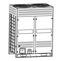
Physical dimensions for various indoor unit models, including Cassette, Duct, and Convertible types.

3.1 Piping Diagrams

Illustrates the refrigerant flow and components within the air conditioning system.

4.1 Wiring Diagrams Overview

Electrical connection diagrams for indoor and outdoor units across different series.

Installation Procedures and Guidelines

7.1 Cassette Installation Steps

General installation steps and safety warnings specific to cassette indoor units.

General Installation Safety and Site Selection

Safety warnings, location choice criteria, and preparation for unit installation.

Indoor Unit Installation and Mounting

Procedures for mounting, leveling, and connecting indoor units, including piping and wiring.

Refrigerant Piping and System Handling

Guidelines for refrigerant pipe sizing, connections, leak tests, vacuuming, and charging.

Unit Components and Troubleshooting

8.1 Indoor Unit Components

Details on indoor unit models, PCBs, dip switch settings, and operating functions.

9.1 Outdoor Unit Components

Details on outdoor unit PCBs, dip switch settings, and functional controls.

10.1 Failure Codes and Analysis

Lists and explains error codes for indoor and outdoor units with possible reasons.

11.1 Sensor Codes and B&R Values

Technical specifications for sensor codes and their B&R values.

Related product manuals