EasyManua.ls Logo

Trane 4TXK6512G1000AA User Manual

Trane 4TXK6512G1000AA
187 pages
To Next Page IconTo Next Page
Page #1 background imageLoading...
Page #1 background image
CONTENTS
1 . Specification .................................................................................................................................................................... 1
2 . Dimension ....................................................................................................................................................................... 7
3 . Piping diagram .............................................................................................................................................................. 29
4 . Wiring diagram .............................................................................................................................................................. 31
5 . Performance cure .......................................................................................................................................................... 42
6 . Capacity compensation rate for pipe length and height difference ............................................................................... 54
7 . Installation .................................................................................................................................................................... 60
8 . Indoor ....................................................................................................................................................................................118
9 . Outdoor...................................................................................................................................................................................128
10 . Failure code ............................................................................................................................................................... 141
11 . Sensor code and B&R value ..................................................................................................................................... 152
Question and Answer IconNeed help?

Do you have a question about the Trane 4TXK6512G1000AA and is the answer not in the manual?

Trane 4TXK6512G1000AA Specifications

General IconGeneral
BrandTrane
Model4TXK6512G1000AA
CategoryInverter
LanguageEnglish

Summary

1. Specification

Cooling and Heating Performance

Details on cooling/heating capacities, power input, EER/COP across models.

Indoor Unit Component Specifications

Specs for indoor fan motor, coil dimensions, airflow, and noise levels.

Indoor Unit Dimensions and Weights

Physical dimensions and weight of indoor units.

Refrigerant Piping and Temperature Limits

Refrigerant pipe sizes and operational temperature ranges.

Model Performance Data Overview

Performance data for various models (12K to 60K).

2. Dimension

Indoor Unit Dimensions

Physical dimensions of various indoor unit models (Cassette, Duct).

Outdoor Unit Dimensions

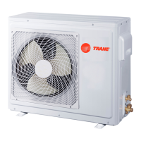
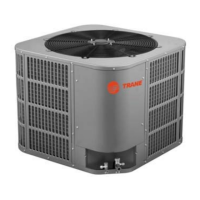
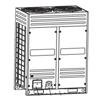
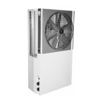
Physical dimensions of various outdoor unit models.

Installation Space Requirements

Space requirements for installing indoor and outdoor units.

3. Piping diagram

Single Split Piping Diagrams

Diagrams showing refrigerant flow for single split systems.

Multi-Split Piping Diagrams

Diagrams showing refrigerant flow for multi-split systems.

4. Wiring diagram

Indoor Unit Wiring

Wiring schematics and component details for indoor units.

Outdoor Unit Wiring

Wiring schematics for outdoor units and power supply connections.

Electrical Wiring Precautions

Safety warnings and guidelines for electrical wiring.

5. Performance cure

Model Performance Data

Cooling and heating performance data for various models.

6. Capacity compensation rate

Pipe Length and Height Difference Compensation

Compensation rates for pipe length and height difference.

7. Installation

7.1 Cassette Installation Procedure

Detailed installation steps for cassette type indoor units.

Installation Place Selection

Guidelines for selecting appropriate installation locations.

Indoor Unit Installation Steps

Steps for installing indoor unit, including piping and drainage.

Refrigerant Piping Installation

Procedures and safety for refrigerant piping connections.

7.4 ODU-EN: Outdoor Unit Installation Site Selection

Criteria for selecting outdoor unit installation sites.

7.2 Convertible - EN: Installation Procedure

Installation steps and parts identification for convertible units.

General Installation Safety Precautions

Safety warnings and precautions for all installation personnel.

Indoor Unit Mounting Position Selection

Guidance on selecting optimal mounting positions for indoor units.

Indoor Unit Installation Steps

Steps for installing indoor units and pipe connection requirements.

Drain Pipe Installation and Air Ducting

Procedures for installing drain pipes and air ducts.

Ceiling Mounting and Half-Concealed Installation

Guidelines for ceiling mounting and half-concealed installations.

Suspension Bolt and Unit Mounting

Instructions for installing suspension bolts and mounting indoor units.

Coupler Heat Insulation and Drain Hose Installation

Procedures for insulating couplers and installing drain hoses.

Electrical Wiring Connection

Steps for connecting electrical wiring to terminals.

Power Supply and Inter-Unit Wiring

Connecting power supply and inter-unit communication cables.

Fresh Air Intake

Fresh Air Intake Installation

Procedure for installing the fresh air intake.

Convertible Unit Safety Precautions

Indoor Unit Placement and Function Overview

Indoor Unit Mounting Position Selection Criteria

Outdoor Unit Installation Location Selection

Indoor Unit Dimensions and Air Ducting

Duct Installation Details

Suspension Screw and Unit Hanging

Level Adjustment and Caution

Guidance on level adjustment and associated cautions.

Refrigerant Piping Installation

Piping Connection Method and Torque

Refrigerant Piping Precautions

Leak Test and Vacuum Drying

Refrigerant Charging

Complete Recharging and Oil Instruction

8. Indoor

8.1 Indoor unit PCB Identification

Part codes for main control PCB for various indoor unit types.

8.3 Indoor unit function

Dry Mode Operation

Indoor unit operation modes for dry mode.

Auto Mode Operation

Indoor unit operation modes for auto mode.

Abnormal Operation Handling

System behavior during abnormal operations and conflicts.

Room Card Functionality

Explanation of the room card function for unit control.

9. Outdoor

9.1 Outdoor unit PCB Identification

Part codes for main control PCB and power module for outdoor units.

10. Failure code

Indoor Unit Malfunctions (4MXC Models)

Failure codes and possible reasons for indoor unit malfunctions.

Indoor Unit Malfunctions (4MXD Models)

Failure codes and possible reasons for indoor unit malfunctions.

Outdoor Unit Failure Codes

Failure codes indicated by outdoor unit PCB and their meanings.

11. Sensor code and B&R value

Temperature Sensor Specifications

Part codes and B&R values for various temperature sensors.

Related product manuals