EasyManua.ls Logo

Trane 4WCC4024E1000A - User Manual

Trane 4WCC4024E1000A
36 pages
To Next Page IconTo Next Page
Loading...
SSAAFFEETTYY WWAARRNNIINNGG
Only qualified personnel should install and service the equipment. The installation, starting up, and servicing of heating, ventilating, and air-conditioning
equipment can be hazardous and requires specific knowledge and training. Improperly installed, adjusted or altered equipment by an unqualified person
could result in death or serious injury. When working on the equipment, observe all precautions in the literature and on the tags, stickers, and labels that
are attached to the equipment.
February 2022
1188--BBBB4411DD11--11AA--EENN
Single Packaged Heat Pump
13.4 SEER2 Convertible, 2 5 Ton
4WCC4024E1000A
4WCC4030E1000A
4WCC4036E1000A
4WCC4042E1000A
4WCC4048E1000A
4WCC4060E1000A
NNoottee:: “Graphics in this document are for representation
only. Actual model may differ in appearance.”
NNoottee:: “Unit specific Service Facts available online.”
Installation and Operations Manual
Question and Answer IconNeed help?

Do you have a question about the Trane 4WCC4024E1000A and is the answer not in the manual?

Trane 4WCC4024E1000A Specifications

General IconGeneral
Model4WCC4024E1000A
TypeHeat Pump
SEER RatingUp to 14.5
HSPF Rating8.2
RefrigerantR-410A
Voltage208/230V
Phase1
Cooling Capacity24000 BTU/H
Heating Capacity24, 000 BTU
Compressor TypeScroll

Summary

SAFETY SECTION

Electrical and Refrigerant Safety Warnings

Critical safety warnings for electrical hazards and refrigerant types.

General Safety Cautions

Grounding requirements and operational safety hazards.

Introduction, Unit Inspection and Specification

Introduction to the Manual

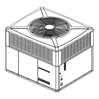
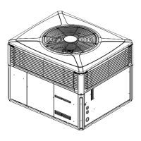
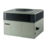
Overview of manual content and initial setup considerations.

Inspecting Unit Shipment

Procedures for checking unit condition upon delivery.

Charging Procedures

How to charge refrigerant in cooling and below 55°F.

Determine Unit Clearances

Review Location and Recommendation Information

Unit Location and Airflow Considerations

Location needs for horizontal and down airflow units.

Clearance Requirements

Recommended clearances for unit installations.

Unit Installation

Ground Level Installation

Instructions for installing the unit at ground level.

Convert Horizontal Airflow to Down Airflow

Steps to change airflow direction from horizontal to down.

Install Full Perimeter Roof Mounting Curb

Steps to install a roof mounting curb.

Lifting and Rigging Procedures

Safety guidelines and procedures for lifting and rigging the unit.

Placing the Unit on the Mounting Curb

Instructions for positioning and setting the unit on the mounting curb.

Rooftop Installation - Frame Mounting

Installing the unit on a roof frame.

Rooftop Installation - No Curb; Frame

Installing the unit on sleeper rails rather than a curb or frame.

Ductwork Installation

Guidelines for ductwork construction and attachment.

Condensate Drain Piping

Instructions for condensate drain connection and piping.

Air Filter Installation

Procedures for installing air filters in the unit.

Electrical Wiring and Connections

Covers wiring, power, disconnects, and protection.

Field Wiring Diagram

Diagram showing field wiring connections for the unit.

Control Wiring (Class II)

Guidelines for low voltage control wiring and thermostat connections.

Unit Startup

Pre-Start Checklist and Setup

Verifying installation and preparing for startup.

Starting and Shutting Down the Unit

Procedures for starting and stopping in cooling and heating modes.

Operating Checks

How to perform operating pressure and voltage checks.

Sequence of Operation

Detailed explanation of unit operation cycles.

Heating Modes and Defrost

Operation in heating, supplementary heat, and defrost.

Final Installation Checklist

Final inspection points before operation.

Maintenance Overview

Owner and service maintenance tasks for optimal unit performance.

Indoor Fan Motor Speed

Setting the indoor fan motor speed tap.

Defrost Control System

Explanation, fault detection, and checkout of the defrost control.

Test Sensors and Pins

Identification and testing of defrost control pins and sensors.

Pressure Curves

Indoor Fan Performance

Refrigerant Circuit

Troubleshooting Chart

Important Product Information

Related product manuals