EasyManua.ls Logo

Trane A4AC3018D User Manual

Trane A4AC3018D
44 pages
To Next Page IconTo Next Page
Page #1 background imageLoading...
Page #1 background image
Installation and Operation Manual
April 2022
88-A4AC3001-1J-EN
SAFETY WARNING
Only qualified personnel should install and service the equipment. The installation, starting up, and servicing of heating, ventilating,
and air-conditioning equipment can be hazardous and requires specific knowledge and training. Improperly installed, adjusted or
altered equipment by an unqualified person could result in death or serious injury. When working on the equipment, observe all pre-
cautions in the literature and on the tags, stickers, and labels that are attached to the equipment.
Models
A4AC3018D A4AC3018A
A4AC3023D A4AC3023A
A4AC3024D A4AC3024A
A4AC3030D A4AC3029A
A4AC3035D A4AC3030A
A4AC3036D A4AC3036A
A4AC3042D A4AC3042A
A4AC3048D A4AC3043A
A4AC3060D A4AC3048B
A4AC3060A
Note: “Graphics in this document are for representation only.
Actual model may differ in appearance.”
Condensing Units
Question and Answer IconNeed help?

Do you have a question about the Trane A4AC3018D and is the answer not in the manual?

Trane A4AC3018D Specifications

General IconGeneral
Cooling Capacity1.5 Ton
RefrigerantR-410A
Phase1
Cooling Capacity (BTU)18000 BTU
Voltage208/230V
Indoor Unit CompatibilityTrane Air Handlers

Summary

Safety

Safety Warnings and Precautions

General safety warnings, electrical component hazards, and refrigerant handling precautions.

Unit Location Considerations

Unit Dimensions and Weight

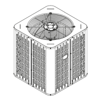
Details unit dimensions and weight specifications for various models.

Refrigerant Piping Limits

Specifies maximum total length and vertical change for refrigerant lines.

Location Requirements for Reliability

Provides guidance on optimal placement to ensure reliable operation and airflow.

Cold Climate Installation Notes

Offers advice for installations in areas prone to snow and freezing temperatures.

Unit Preparation

Prepare Unit for Installation

Instructs on checking the unit for damage before installation.

Setting the Unit

Pad Installation Guidelines

Outlines requirements for installing the unit on a support pad.

Refrigerant Line Considerations

Line Sizes and Service Valve Connections

Lists sizes for refrigerant lines and service valve connections for each model.

Factory Charge and Line Insulation

Explains factory charge and emphasizes vapor line insulation requirements.

Required Refrigerant Line Length

Guides on determining total line length and vertical change needed for system configuration.

Reusing Existing Refrigerant Lines

Provides precautions for using existing refrigerant lines during retrofit installations.

Refrigerant Line Routing

Routing Precautions and Methods

Advises on routing lines to prevent noise and vibration transmission through structures.

Refrigerant Line Brazing

Brazing Process Steps

Details the step-by-step process for brazing refrigerant lines, including preparation.

Refrigerant Line Leak Check

Leak Detection Procedure

Describes how to pressurize lines and check for leaks using soapy solution.

Evacuation

Evacuating Lines and Coil

Explains how to evacuate the system to specific micron levels for moisture removal.

Service Valves

Opening Gas Service Valve

Provides instructions on how to properly open the gas service valve.

Opening Liquid Service Valve

Details the cautious procedure for opening the liquid line service valve.

Electrical - Low Voltage

Low Voltage Wire Length Limits

Lists maximum allowed lengths for low voltage wiring based on wire gauge.

Low Voltage Hook-up Diagrams

Illustrates wiring connections for various thermostat and system configurations.

Electrical - High Voltage

High Voltage Power Supply Requirements

Details requirements for the high voltage power supply and compliance with codes.

High Voltage Disconnect and Grounding

Recommends disconnect switch and specifies grounding requirements.

Start Up

System Start-Up Procedure

Outlines the sequence of steps to safely start up the installed system.

System Charge Adjustment

Temperature Measurements for Charging

Explains how to measure temperatures to determine the correct charging method.

Subcooling Charging (Above 55°F)

Details the subcooling method for charging systems in warmer outdoor temperatures.

Charging Below 55°F

Describes the weigh-in method for charging systems in colder outdoor temperatures.

Checkout Procedures

Operational and Checkout Procedures

Provides a checklist of final inspections and operational tests after installation.

Refrigerant Circuits

Wiring Diagrams

Pressure Curves

Related product manuals