88-A4AC3001-1C-EN 15
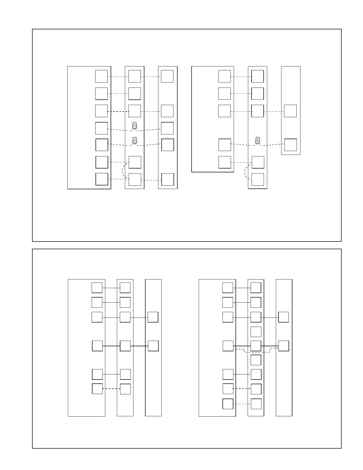
11.2 Low Voltage Hook-up Diagrams
With Furnace With Variable Speed Furnace
• Units with pigtails require wirenuts for connections. Cap all unused wires.
•
In AC systems for multiple stages of heat, jumper W1 and W2 together if comfort control has only one stage of heat.
* If equipped with second stage heat
** When using a BK enabled comfort control, cut BK jumper and bypass Y and YLo at the furnace. Connect BK from comfort control
to
Thermostat Furnace Furnace
Outdoor
Unit
R
G
B
W1
W2
B
Y
R
G
B/C
W1
W2
24 VAC HOT
FAN
24 VAC
Common
COOL
HEATING
YY1
YY
Y
LO
Thermostat
Outdoor
Unit
R
G
B
W1
W2
B
R
G
B/C
Y1
W1
W2
24 VAC HOT
FAN
24 VAC
Common
COOL
HEATING
O
BK
BK
**
**
R
G
B
W1
W2
R
B
O
Y
X2
R
G
B/C
O
Y
W
Blue
24 VAC HOT
FAN
24 VAC
Common
SOV
COOL/HEAT
1st STAGE
HEATING
2nd STAGE
Y
Thermostat Air Handler
Outdoor
Unit
Pink Black
W2
Pink
White
White
X2
R
G
B
W1
B
Y
R
G
B/C
Y
W
Blue
24 VAC HOT
FAN
24 VAC
Common
COOLING
HEAT
Thermostat Air Handler
Outdoo
Unit
In AC systems for multiple stages of electric heat, jumper W1
and W2 together if comfort control has only one stage of heat.