Do you have a question about the Trane A4AC5018D1000A and is the answer not in the manual?
General safety warnings and precautions for handling HVAC equipment.
Critical safety information regarding R-410A refrigerant, system pressures, and POE oil.
Warnings and cautions related to working with live electrical components during installation and servicing.
Specifications for unit dimensions, weight, and guidelines for refrigerant piping length and vertical change.
Recommendations for outdoor unit placement to optimize performance and minimize noise impact.
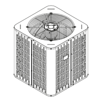
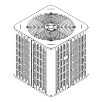
The initial step in unit preparation, focusing on checking for and reporting any shipping damage.
Considerations for installing the unit on a support pad, including levelness and drainage requirements.
Table specifying vapor and liquid line sizes and service valve connections for different models.
Details on factory refrigerant charge and guidance for adding refrigerant based on tubing length.
Critical guidance on insulating the vapor line and preventing direct contact between refrigerant lines.
Precautions and requirements for reusing existing refrigerant lines during system retrofits.
Best practices for routing refrigerant lines to prevent noise transmission and ensure proper installation.
Detailed procedure for brazing refrigerant lines, including purging, heat protection, and valve core replacement.
Method for pressurizing lines with dry nitrogen and checking for leaks using a soapy solution.
Instructions for evacuating the refrigerant lines and indoor coil to a specified micron level.
Procedure for safely opening the gas service valve, including stem rotation and cap replacement.
Critical procedure for opening the liquid service valve with a warning about potential pressure release.
Table specifying maximum permissible lengths for low voltage wiring based on gauge size.
Schematic diagrams illustrating low voltage connections for heat pump and AC systems.
Covers power supply requirements, disconnect switches, and grounding for high voltage connections.
A step-by-step guide for initiating system operation after the installation is complete.
Process for measuring outdoor and indoor temperatures to prepare for system charge adjustment.
Detailed method for charging the system using subcooling when the outdoor temperature is above 55°F.
Guidance on using subcooling charts for adjustments and the importance of system stabilization periods.
Steps to calculate the final subcooling value using measured liquid line temperature and pressure data.
A comprehensive list of checks and procedures to verify proper system operation and installation quality.
Schematic diagrams illustrating refrigerant flow for different unit sizes (1 1/2-Ton, 2 & 3-Ton).
Schematic diagram illustrating refrigerant flow for 2 1/2-Ton condensing units.
Schematic diagrams illustrating refrigerant flow for 3 1/2 & 4-Ton condensing units.
Schematic diagram detailing the refrigerant flow for 5-Ton condensing units.
Detailed electrical wiring diagrams for specific models, including legends and notes for installation.
Graphical representation of liquid and suction pressures versus outdoor temperature for performance verification.