18-AD37D1-1-EN 7
Installer’s Guide
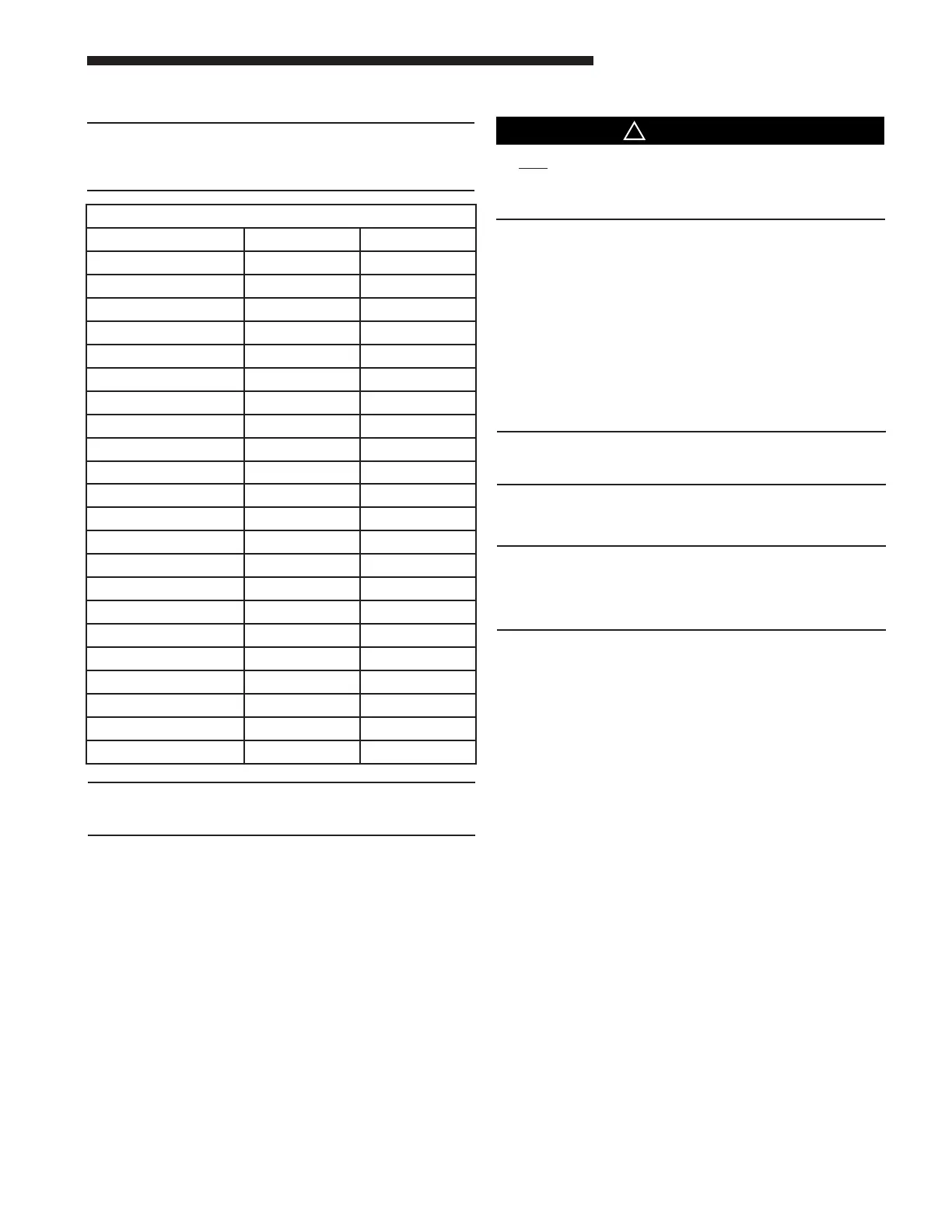
Maximum airflow setting, CFM
Coil Upflow Horizontal Left
A4MXA1824AC6HA 900 800
A4MXB1832AC6HA 1125 1000
A4MXA3036AC6HA 1350 1125
A4MXB3642AC6HA 1350 1200
A4MXC3642AC6HA 1350 1200
A4MXB4248AC6HA 1800 1600
A4MXC4248AC6HA 1800 1600
A4MXD4248AC6HA 1800 1600
A4MXC4260AC3HA 2250 2000
A4MXD4260AC3HA 2250 2000
Coil Downflow Horizontal Right
A4MXA1824AC6HA 750 900
A4MXB1832AC6HA 925 1125
A4MXA3036AC6HA 1200 1350
A4MXB3642AC6HA 1100 1350
A4MXC3642AC6HA 1100 1350
A4MXB4248AC6HA 1475 1800
A4MXC4248AC6HA 1475 1800
A4MXD4248AC6HA 1475 1800
A4MXC4260AC3HA 1850 2250
A4MXD4260AC3HA 1850 2250
J. MAXIMUM AIRFLOW SETTING, CFM
NOTE:
Water blow-off could occur in certain installation posi-
tions if the airflow setting exceeds the maximum values
listed.
IMPORTANT:
Do not unseal refrigerant tubing until ready to fit refriger-
ant lines.
There is only a holding charge of dry air in the indoor coil,
therefore no loss of operating refrigerant charge occurs when
the sealing plugs are removed.
NOTE:
Where applicable, the TXV bulb MUST be protected
(wrapped with wet rag) or removed, while brazing the tub-
ing. Overheating of the sensing bulb will affect the func-
tional characteristics and performance of the comfort coil.
1. Remove both rubber plugs from the indoor coil.
2. Field supplied tubing should be cut square, round and free
of burrs at the connecting end. Clean the tubing to prevent
contaminants from entering the system.
3. Run the refrigerant tubing into the stub tube sockets of
the indoor unit coil.
UNIT PANELS MUST BE SHIELDED DURING BRAZ-
ING.
4. Flow a small amount of nitrogen through the tubing while
brazing.
5. Use good brazing technique to make leakproof joints.
6. Minimize the use of sharp 90 degree bends.
7. Insulate the suction line and its fittings.
8. Do NOT allow un-insulated lines to come into contact with
each other.
K. INSTALLING / BRAZING REFRIGERANT LINES
Do NOT open refrigerant valve at the outdoor unit until the
refrigerant lines and coil have been brazed, evacuated, and
leak checked. This would cause contamination of the refriger-
ant or possible discharge of refrigerant to the atmosphere.
1. The following steps are to be considered when installing
the refrigerant lines:
a. Determine the most practical way to run the lines.
b. Consider types of bends to be made and space limita-
tions.
c. Route the tubing making all required bends and
properly secure the tubing before making final connec-
tions.
NOTE: Refrigerant lines must be isolated from the structure
and the holes must be sealed weather tight after installation.
NOTE:
Units with factory shipped TXV may run high superheat
(15-25F) by design when measured at the OD unit.
 Loading...

