Installation Guide
22 18-HD68D1-10
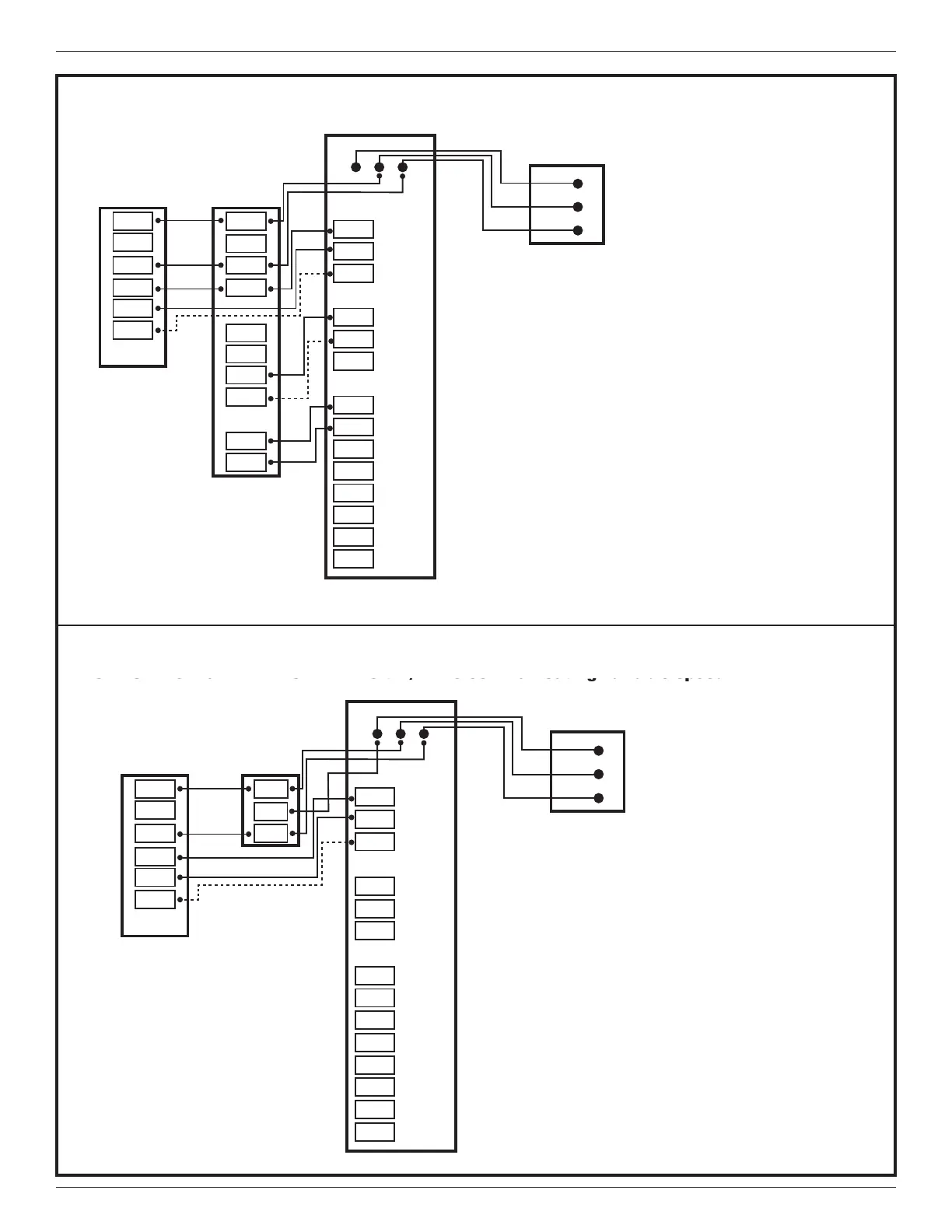
10- 1 OR 2 STAGE HEAT PUMP W/TEM6 MODEL VARIABLE SPEED AIR HANDLER
NOTES:
1. Remove the factory installed BK jumper at the
indoor unit
2. Connection to X2 is not required for this
configuration
3. D Terminal is on TEM8 ONLY.
2
1
SOV
STG2
STG1
STG1
STG3
STG2
FA N
PWM
HUM
HUM
AUX1
AUX1
AUX2
AUX2
24V
ONLY
24V
ONLY
24V
ONLY
O
Y1
Y2
W1
W2
W3
G
BK
HUM*
HUM*
AUX1*
AUX1*
AUX2*
AUX2*
RELAY PANEL
R
B
O
Y2
Y1
W1
W2
G
INDOOR UNIT
R
X2
B
O
Y2
Y1
OUTDOOR UNIT
BK
COMMUNICATING
CONTROL
D R B
D
R
B
*See note on page 7 regarding HUM and AUX
terminals.
Caution: Do not run Outdoor/Remote sensor wires in
the same bundle with HVAC wires. Also, keep away
from high voltage wiring to avoid interference.
D
10- 1 OR 2 STAGE HEAT PUMP 24 volt w/TEM8 communicating variable speed AIR HANDLER
NOTES:
1. Remove the factory installed BK jumper at the
indoor unit
2. Connection to X2 is not required for this
configuration
2
SOV
STG2
STG1
STG1
STG3
STG2
FA N
PWM
HUM
HUM
AUX1
AUX1
AUX2
AUX2
24V
ONLY
24V
ONLY
24V
ONLY
O
Y1
Y2
W1
W2
W3
G
BK
HUM*
HUM*
AUX1*
AUX1*
AUX2*
AUX2*
RELAY PANEL
R
B
INDOOR UNIT
R
X2
B
O
Y2
Y1
OUTDOOR UNIT
COMMUNICATING
CONTROL
D R B
D
R
B
*See note on page 7 regarding HUM and AUX
terminals.
Caution: Do not run Outdoor/Remote sensor wires in
the same bundle with HVAC wires. Also, keep away
from high voltage wiring to avoid interference.
D
Diagram 11 - 1 or 2 Stage Heat Pump w/TEM6 or TEM8 Variable Speed Air Handler 24 volt
Diagram 12 - 1 or 2 Stage Heat Pump 24 volt w/TEM8 Communicating Variable Speed Air
Handler
 Loading...