RELAY PANEL
18-HD68D1-10 27
Section 7. Troubleshooting
Troubleshooting
Symptom Possible Cause Action
COMM LED is not
flashing the ap-
propriate number
of devices
Loss of 24VAC between power (R) and common (B) Check for proper incoming 24VAC power
One or more communicating devices is not com-
municating
• ~12VDC between D & B = Proper communication
• ~16VDC between D & B = Loss of communication
• Less than ~12VDC between D & B = shorted or no power
Check for open or shorts in field wiring
Evaluate other communicating devices and use
the service facts of that device if not communi-
cating properly
Bit Master LED is
off or fluttering
Loss of 24VAC between power (R) and common (B) Check for proper incoming 24VAC power
Loss of communication
• 0VDC between D & B (shorted or no power)
• Less than ~12VDC between D & B (low level short)
Check for shorted wire between data (D) and
common (B) wires
HVAC System
LED is not illumi-
nating when Relay
Panel is calling for
a particular relay
Control is not calling
Check the System Report screen at the control
to verify demand
Relay Panel failed
Verify 24VAC between relay output terminal and
common (B)
**Relay output contains snubber circuits; always
check with a load applied
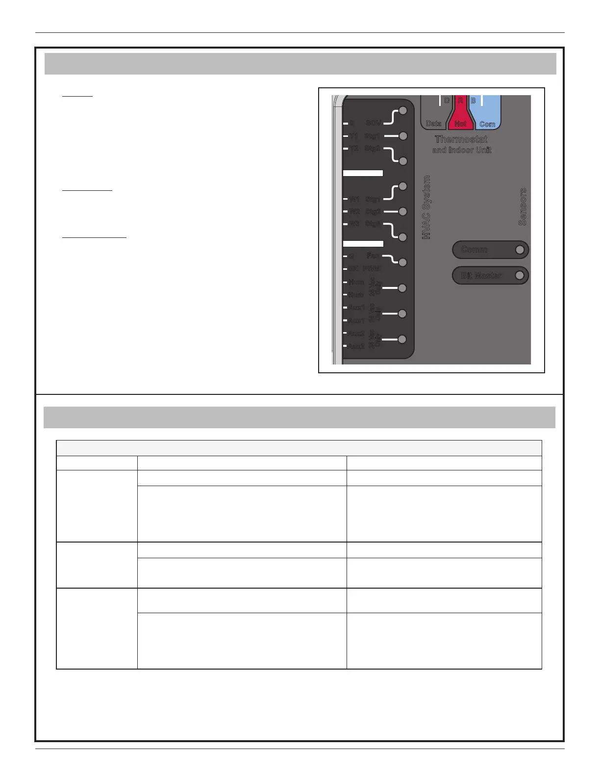
Section 6. LED Indicators
Aux2
Bit Master
Comm
HVAC System
Sensors
Thermostat
and Indoor Unit
Data
Hot
Com
24 Vac
Only
24 Vac
Only
24 Vac
Only
Aux2
Aux1
Aux1
Hum
Hum
BK
PWM
Fan
G
W3 Stg3
W2 Stg2
W1 Stg1
Y1 Stg1
Y2 Stg2
0 SOV
Comm
Communication LED – Amber
• LED on when first powering up
• LED flashes number of communicating com-
ponents in the system.
• (ex. communicating control with relay panel
will equal two flashes)
Bit Master
Bitmaster/Clock Signal LED – Green
• LED on when Clock is working
HVAC System
HVAC System LEDs – Green
• A Green LED will illuminate when the relay is
energized.
 Loading...