Installation Guide
26 18-HD68D1-10
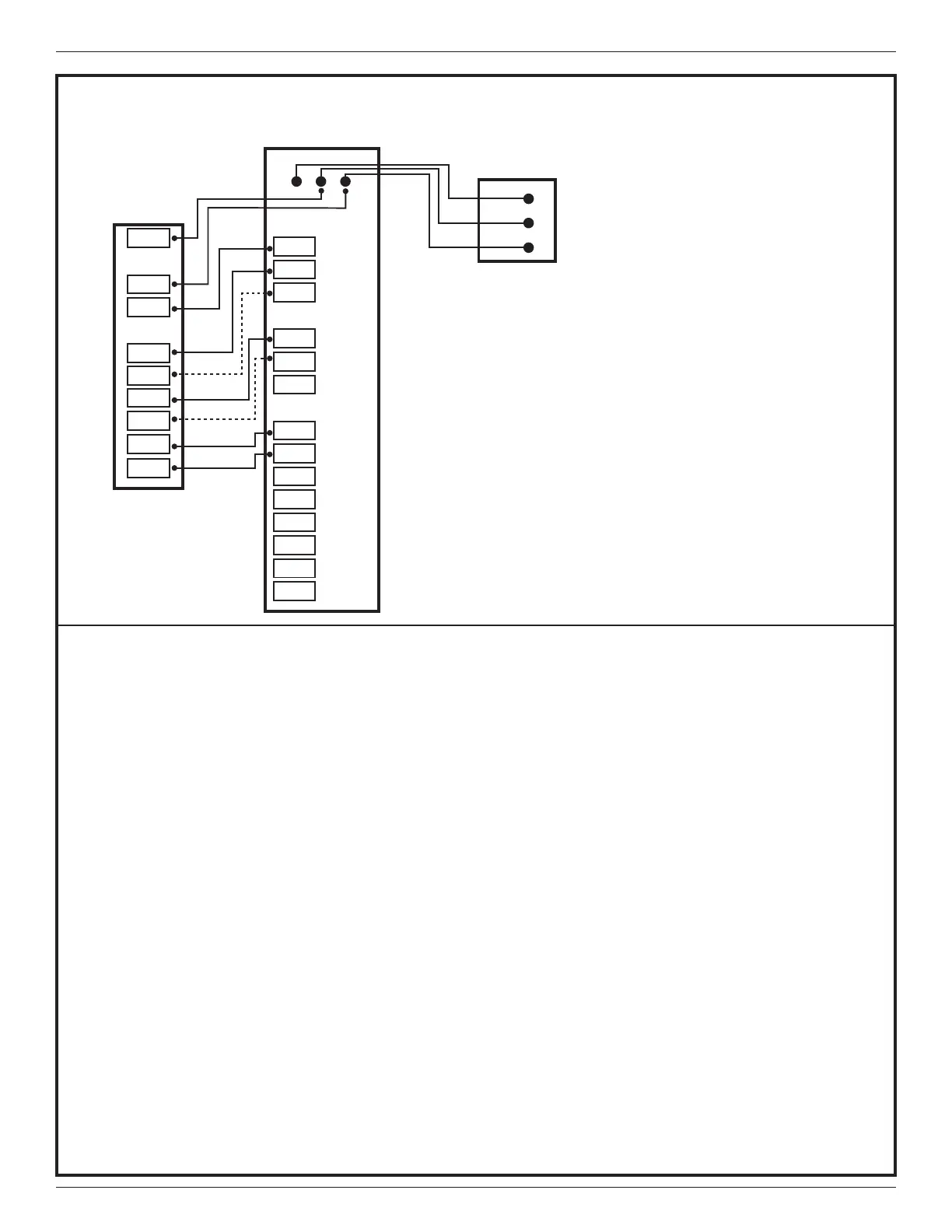
Diagram 5 - Package 1 or 2 Stage Dual Fuel w/Variable Speed Blower
4 - PACKAGE 1 OR 2 STAGE DUAL FUEL W/VARIABLE SPEED BLOWER
NOTES:
1. Remove “R” to “BK” jumper and clip all “Y”
connections at the integrated motor control board
(ICMC) to enable pulse width control of the variable
speed indoor blower. Ensure clipped wires are
capped and taped off.
RELAY PANEL
1
SOV
STG2
STG1
STG1
STG3
STG2
FA N
PWM
HUM
HUM
AUX1
AUX1
AUX2
AUX2
24V
ONLY
24V
ONLY
24V
ONLY
O
Y1
Y2
W1
W2
W3
G
BK
HUM*
HUM*
AUX1*
AUX1*
AUX2*
AUX2*
R
B
BK
G
OUTDOOR
UNIT
O
Y/Y1
W1
W2/X2
Y2
COMMUNICATING
CONTROL
D R B
D
R
B
*See note on page 7 regarding HUM and AUX
terminals.
Caution: Do not run Outdoor/Remote sensor wires in
the same bundle with HVAC wires. Also, keep away
from high voltage wiring to avoid interference.
 Loading...