Installation Guide
6 18-HD68D1-10
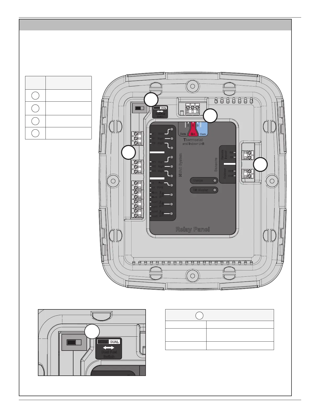
KEY
Terminal
Identification
A
Dual Fuel Switch
B
Thermostat +
24VAC Input
C
Optional Sensors
D
HVAC System
Aux2
Relay Panel
Bit Master
Comm
HVAC System
Sensors
Thermostat
and Indoor Unit
Outdoor
Remote
Data
Hot
Com
D R
B
Indoor
RS
RS
ODT
ODT
24 Vac
Only
24 Vac
Only
24 Vac
Only
Aux2
Aux1
Aux1
Hum
Hum
BK
PWM
Fan
G
W3 Stg3
W2 Stg2
W1 Stg1
Y1 Stg1
Y2 Stg2
0 SOV
NORM
Dual Fuel
Switch
DUAL
A
B
D
C
Refer to the following diagrams for descriptions
of each terminal.
This switch ships in the NORM position by
default. Refer to the following section for com-
plete Field Wiring Diagrams.
Aux2
Relay Panel
Bit Master
Comm
HVAC System
Sensors
Thermostat
and Indoor Unit
Outdoor
Remote
Data
Hot
Com
D R
B
Indoor
RS
RS
ODT
ODT
24 Vac
Only
24 Vac
Only
24 Vac
Only
Aux2
Aux1
Aux1
Hum
Hum
BK
PWM
Fan
G
W3 Stg3
W2 Stg2
W1 Stg1
Y1 Stg1
Y2 Stg2
0 SOV
NORM
Dual Fuel
Switch
DUAL
A
A
Dual Fuel Switch
Switch Position Description
NORM
For HP or conventional
Heat/Cool systems.
DUAL For dual fuel systems.
Section 4. Terminal Locations and ID