RELAY PANEL
18-HD68D1-10 7
Aux2
Relay Panel
Bit Master
Comm
HVAC System
Sensors
Thermostat
and Indoor Unit
Outdoor
Remote
Indoor
RS
RS
ODT
ODT
24 Vac
Only
24 Vac
Only
24 Vac
Only
Aux2
Aux1
Aux1
Hum
Hum
BK
PWM
Fan
G
W3 Stg3
W2 Stg2
W1 Stg1
Y1 Stg1
Y2 Stg2
0 SOV
NORM
Dual Fuel
Switch
DUAL
C
D
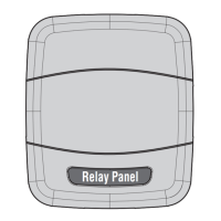
HVAC System Connections
Terminal Name Description Color Used:
O - SOV Switch Over Valve
Y1 - Stg1 First Stage Compressor
Y2 - Stg2
Second Stage
Compressor
W1 - Stg1 First Stage ID Heating
W2 - Stg2 Second Stage ID Heating
W3 - Stg3 Third Stage ID Heating
G - Fan Indoor Blower
BK - PWM
PWM Signal for indoor
blower modulation
Hum* Humidifier Contact
Hum* Humidifier Contact
Aux 1* Dehumidifier/Ventilation ---
Aux 1* Dehumidifier/Ventilation ---
Aux 2* Dehumidifier/Ventilation ---
Aux 2* Dehumidifier/Ventilation ---
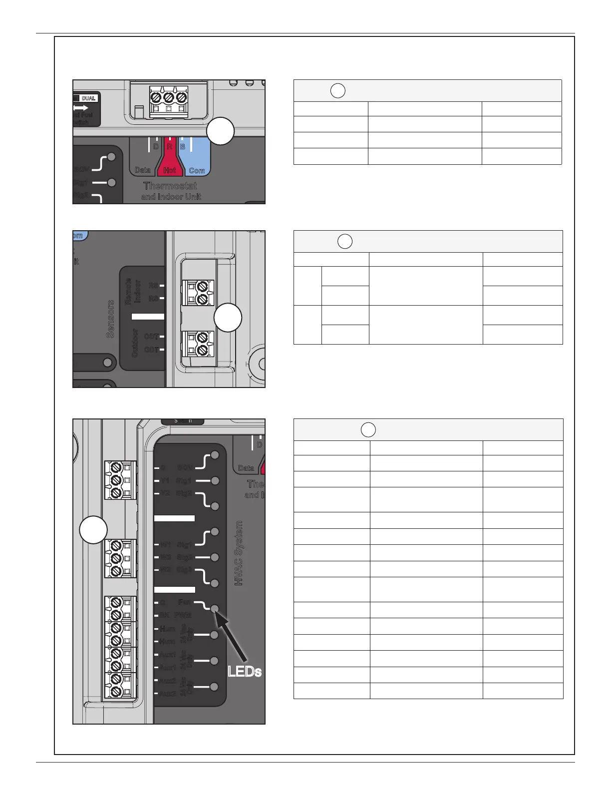
C
Optional Remote Sensor Connections
Terminal Name Description Color Used:
Remote
Indoor
RS
Remote Indoor
temp sensor
ZZSENSAL0400AA
RS
Outdoor
ODT
1 Outdoor temp sensor
BAYSEN01ATEMPA
ODT
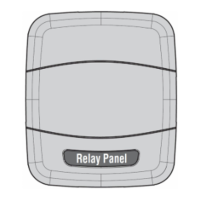
B
Thermostat and Indoor Unit Connections
Terminal Name Description Color Used:
D - Data Data
R - Hot 24 V hot
B - Com 24 V common
Aux2
Relay Panel
Bit Master
Comm
HVAC System
Sensors
Thermostat
and Indoor Unit
Data
Hot
Com
D R
B
Indoor
RS
RS
ODT
ODT
24 Vac
Only
24 Vac
Only
24 Vac
Only
Aux2
Aux1
Aux1
Hum
Hum
BK
PWM
Fan
G
W3 Stg3
W2 Stg2
W1 Stg1
Y1 Stg
1
2
V
l
DUAL
B
For convenience, you may record the color of each wire
used in the blanks provided.
Note: R & B must receive 24 volts from the indoor unit transformer.
Note: The Relay Panel uses 5 VDC to obtain temperature feedback from
remote sensors. Do not run these sensors in a wiring bundle that contains
24 volts AC. See remote sensor literature for troubleshooting.
1 Wired outdoor temperature sensor must be enabled at the Control.
*Note:
Hum & Aux terminals are dry contacts only. Input voltage will need to be
supplied. Refer to humidifier’s installer’s guide. If the output of these contacts is
being used as an input to a non electro-mechanical device, a field-supplied 10K
Ohm resistor should be placed between the top terminal of each pair of contacts
and the Common (B) terminal of the Relay Panel.
Aux2
Relay Panel
Bit Master
Comm
HVAC System
Sensors
Thermostat
and Indoor Unit
Outdoor
Remote
Data
D
24 Vac
Only
24 Vac
Only
24 Vac
Only
Aux2
Aux1
Aux1
Hum
Hum
BK
PWM
Fan
G
W3 Stg3
W2 Stg2
W1 Stg1
Y1 Stg1
Y2 Stg2
0 SOV
D
LEDs