16
INSTALLER’S GUIDE
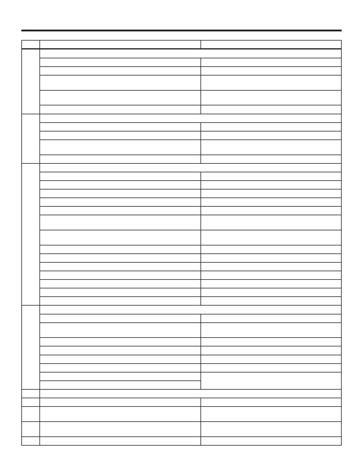
Table 4. Checkout for W7212, W7213, W7214 Economizer Connected to Honeywell Actuator (Cont.)
Step Checkout Procedure Proper Response
2. DIFFERENTIAL ENTHALPY
Execute stop one, Checkout Preparation.
―
Turn DCV MAX to mid position.
Place 620 ohm resistor across S
O
and + (white sleeve resistor
makes OA enthalpy low).
Place 1.2K ohm resistor across S
R
and + (purple sleeve resistor
makes RA enthalpy high).
Free cool LED turn on; motor drives to approximately 45
degrees (half) open.
Remove 620 ohm resistor from S
O
and +. Free cool LED turn off; motor drives closed
3. SINGLE ENTHALPY
Execute stop one, Checkout Preparation.
―
Turn DCV MAX to mid position.
Set enthalpy potentiometer to A (fully CCW). Free cool LED turns on; motor drives to approximately 45
degrees (half) open.
Set enthalpy potentiometer to D or E for W7212C (fully CW). Free cool LED turns off; motor drives closed.
4. DCV AND EXHAUST
Execute step one, Checkout Preparation.
―
LED for both DCV and Exhaust should be off.
Turn DCV MAX to mid position. Motor drives to mid position, 45 degrees open.
Turn MIN POS fully CW. Motor drives fully open.
Turn MIN POS and DCV MAX to fully CCW. Motor drives closed.
Turn DCV MAX to mid position.
Connect 9V battery positive to AQ and negative to AQ1.
LED for both DCV and Exhaust turn on.
Actuator drives to 45 degrees open.
Remove jumper from N terminal (economizer goes into not occu-
pied mode).
Motor remains at 45 degrees open.
Adjust DCV MAX towards CW. Motor will move to position set by DCV MAX pot.
Adjust DCV MAX to fully CCW. Motor will drive closed.
Reconnect jumper to N terminal.
Adjust DCV MAX and MIN POS pots. Motor will drive to the most open position of the pots.
Adjust DCV MAX and MIN POS pots to fully CCW.
Remove power from N terminal adjust MIN POS towards CW. Motor should not move.
Adjust DCV MAX towards CW. Motor will move to position set by DCV MAX pot.
5. MINIMUM AND MAXIMUM POSITION
Execute stop one, Checkout Preparation.
―
Connect 9V battery positive to AQ and negative to AQ1. Adjust
DCV MAX potentiometer to mid position.
DCV LED turns on. Actuator drives to 45 degrees open.
Turn DCV maximum position potentiometer to fully CCW. Actuator drives fully closed.
Turn minimum position potentiometer to midpoint. Actuator drives to 45 degrees open.
Turn minimum position potentiometer fully CW. Actuator drives fully open.
Turn MIN POS to fully CCW. Actuator drives fully closed.
W7212: Remove jumper from TR and N. Actuator drives fully closed.
W7214: Jumper TR to O.
6. MIXED AIR INPUT
Execute stop one, Checkout Preparation.
―
Turn DCV MAX to mid position; set enthalpy potentiometer to A. Free cool LED turns on.
Actuator drives to 45 degrees open.
Remove 5.6K ohm resistor (green sleeve) and place jumper from
T and T1.
Actuator drives to 45 degrees open.
Remove jumper from T and T1 and leave open. Actuator drives fully closed.