Page 2
INSTALLER'S GUIDE
18-HB13D7-2
BAYHTR -- HEATER DATA
Heater
Model No.
Number
of
Circuits
Phase
240 VOLT 208 VOLT
Capacity
Heater
Amps per
Circuit
Capacity
Heater
Amps per
Circuit
KW BTUH KW BTUH
BAYHTR1405 +++ 1 1 4.80 16400 20 3.60 12300 17.3
BAYHTR1408 +++ 1 1 7.68 26200 32 5.76 19700 27.7
BAYHTR1410 +++ 1 1 9.60 32800 40 7.20 24600 34.6
BAYHTR3410 000 1 3 9.60 32800 34.6 7.20 24600 30
BAYHTR1415 BRK 2 1 15.36 52400 40/24 11.53 39300 34.6/20.8
BAYHTR3415 000 1 3 15.36 52400 38.2 11.53 39300 33.1
BAYHTR1419 BRK 2 1 19.20 65500 32/48 14.42 49200 27.7/41.6
BAYHTR1425 BRK 3 1 24.96 85200 44/40/20 18.73 63900 38.1/34.6/17.3
+++ = 000, BRK, PDC
000 = pigtails, BRK = contains Circuit Breakers, PDC = contains Pull Disconnect
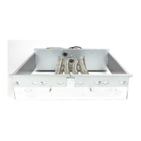
8. Connect the female polarized plug (disconnected
in item 2 from the wire bundle next to the
knockouts) to the male polarized plug on the
bottom of the heater control box
9. Refer to the heater minimum airflow chart on the
air handler rating nameplate for the appropri-
ate minimum blower speed tap to be used with
the approved heater installed.
10. For heaters with self contained disconnect, an
opening in the blower access panel is provided so
that the disconnect may be operated without
removal of the blower access panel. Remove the
metal cover from the circuit breaker opening in
the air handler access panel and discard, cut out
the fiberglass insulation only in the areas where
the disconnect will extend through the opening.
11. Replace all panels removed during the heater
installation.
 Loading...