Supplementary
Electric Heaters
for Air Handler Installations
INSTALLER'S
GUIDE
Models:
BAYHTR1405+++
BAYHTR1405BRK
BAYHTR1408+++
BAYHTR1408BRK
BAYHTR1410+++
BAYHTR1410BRK
+++ = 000, PDC
BAYHTR3410000
BAYHTR1415BRK
BAYHTR3415000
BAYHTR1419BRK
BAYHTR1425BRK
IMPORTANT — This Document is customer property and is to remain with this unit. Please return to service information pack upon completion of work.
© 2008 Trane
A. GENERAL
This accessory electric heater is designed to pro-
vide power directly to the air handler from the
accessory heaters power supply eliminating the
need for additional circuits. The power and control
wiring use a single polorized plug to connect the
heater and the air handler. Single source power
entry is provided for single phase heaters with two
circuits using accessory BAYSPEK140B. See the
Heater Data table on page 2 for the number of
circuits required.
1. Check the air handler heater label to comfirm
that the selected Heater is approved for use with
this air handler, in the installed configuration.
2. Check the components received for damage.
Report any defects or shortages to the transpor-
tation company immediately.
3. Be sure the power supply agrees with the listing
shown on heater nameplate.
B. INSTALLATION
1. Remove the blower access panel from the front
of the air handler.
2. Disconnect the female polarized plug from the
wire bundle at left side of air handler near the
knockouts. Discard the male polarized plug and
power wire leads.
3.
(TWG & TGB models only) Remove the cover
from the heater compartment of the air handler
and discard.
ALL phases of this installation must comply with
NATIONAL, STATE AND LOCAL CODES
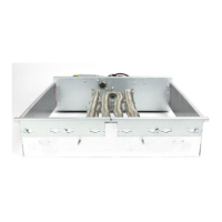
4. Remove the cover from the heater field wiring
and control compartment box. For heaters up
to 15 Kw, an adapter plate is provided which
is used with air handlers that are 21.5” wide
or wider. When required, attach the adapter
plate to the back of the heater on the side
opposite the knockouts using 2 screws.
5. Remove the appropriate knockouts in the heater
field wiring compartment. See Figure 1 on page 3.
Remove the appropriate knockouts in the air han-
dler for making electrical connections to the heater.
The holes in the air handler must align with the
holes in the heater field wiring compartment.
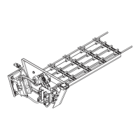
6. Insert the heater assembly into the heater cavity
of the air handler so that the field wiring holes in
the air handler and the heater will align. Secure
the heater compartment to the air handler with
the four screws removed from the hardware
envelope.
IMPORTANT: Conduit must attach directly to
the heater control box.
NOTE: Air handlers approved to use the 1425 heater
have a plate covering either the upper or lower 1.2”
of the heater cavity. This plate is removed ONLY
when the 1425 heater is used. Otherwise it must be
left in place for a blower barrier seal.
7. Make all wiring connections per applicable field
wiring diagrams in these instructions. All in-
structions must conform to national, state and
local electrical codes.
18-HB13D7-2
HAZARDOUS VOLTAGE - DISCONNECT POWER BEFORE SERVICING
WARNING:
Library
Product Section
Product
Model
Literature Type
Sequence
Date
File No.
Supercedes
Service Literature
Unitary
Unitary Accessories
Electric, Steam, Hot Water Coils
Installer's Guide
39D
February 2008
18-HB13D7-2
18-HB13D7-1
02/08