2 Numbers in [brackets] are for 50 Hz international systems. EAC-SF-13
Service Facts
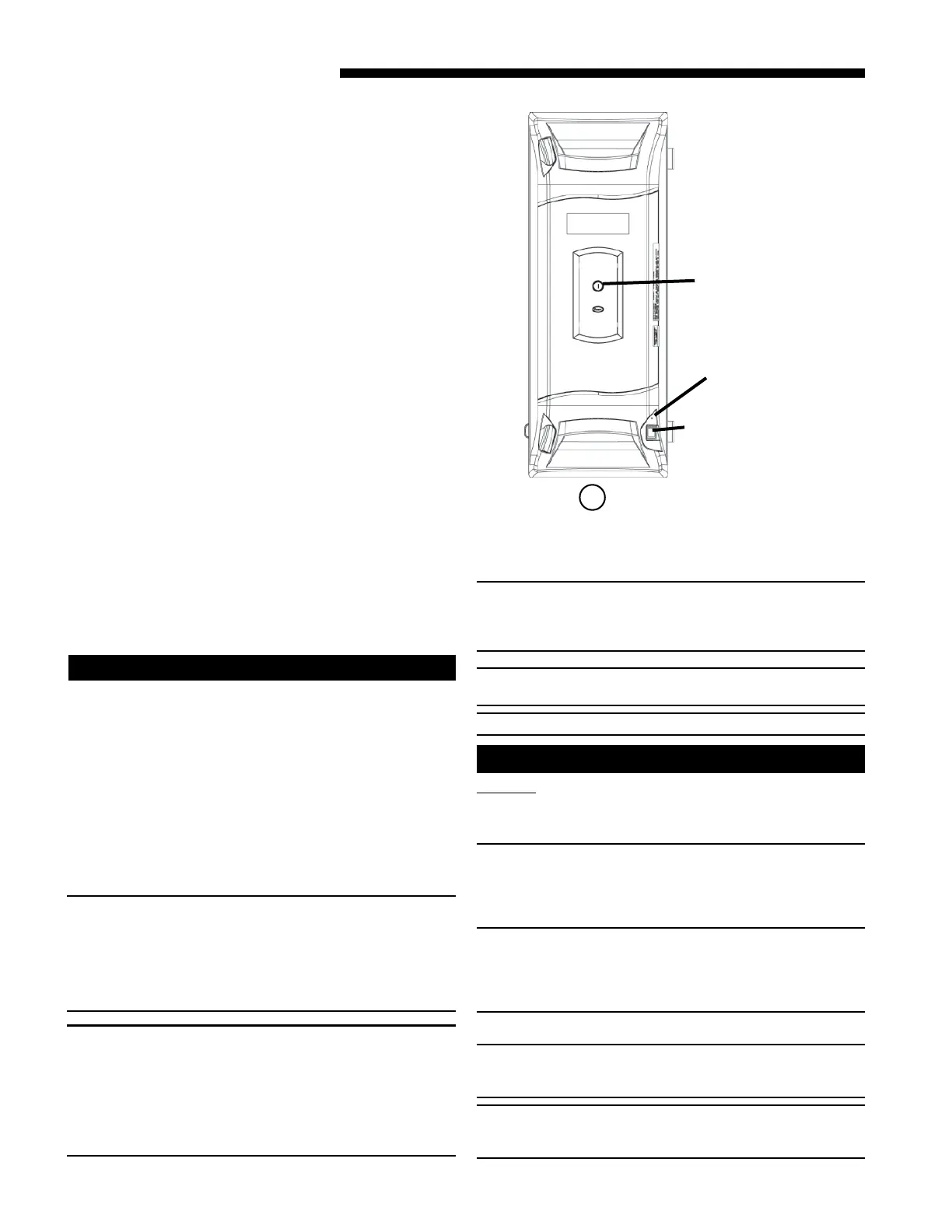
1a
ELECTRICAL CONNECTIONS
The air cleaner requires 24 VAC power and indoor fan
signal to operate. A transformer adequately sized to
power both the system and air cleaner is provided with
the air cleaner. Remove the transformer in the indoor unit
and replace with the transformer provided.
N
OTE: A 50 VA transformer is required for Trane/
American Standard Heating & Air Conditioning
furnace applications and 75 VA required for Trane/
American Standard Heating & Air Conditioning air
handler applications. If the indoor air handler
already has a properly sized transformer, no
replacement is required.
NOTE: Trane/American Standard Heating & Air
Conditioning dual circuited air handlers matched
with heat pumps and Trane/American Standard
Heating & Air Conditioning oil furnaces will require
an accessory Transformer KIT# BAYTRANS12024
◆◆
◆◆
◆
to
power the air cleaner. Do NOT replace air handler
transformer with the transformer supplied with the
air cleaner.
NOTE: When more than one whole house air cleaner
is used, the 24 volt transformer which supplies
power to the air cleaner will need to be increased by
25 VA for each additional air cleaner added.
NOTE: Provide adequate strain relief for the low
voltage cable at the indoor unit.
NOTE: Wiring penetration must be sealed.
CAUTION
!
DO NOT attach the power/control cable to a 120 Volt
EAC tap. The air cleaner uses 24 Volt power. Failure
to use 24 VAC results in permanent damage to the air
cleaner.
• Plug the air cleaner power/control cable into the air
cleaner door and route the cable into the indoor unit
low voltage wiring location.
• Connect the power/control wiring per Figure 2.
NOTE: For non-Trane/American Standard Heating & Air
Conditioning systems order a 120 VAC to 24 VAC
transformer, KIT# BAYTRANS12024
◆◆
◆◆
◆
to provide 24 volt
power only to the air cleaner. Access to 120 VAC outlet
is required.
• Connect the power/control wiring per Figure 3.
NOTE: Trane/American Standard Heating & Air
Conditioning Communicating Furnaces require KIT #
BAYACCECOMM101.
NOTE: Wiring diagrams for the Communicating Air
Handler, Communicating Furnaces and Oil Furnace are
on pages 3, 4-5 and 6 respectively.
▲
CAUTION
!
SAFETY HAZARD
Sharp Edge Hazard. Be careful of sharp edges on equip-
ment or any cuts made on sheet metal while installing or
servicing. Personal injury may result.
INTRODUCTION
The whole house air cleaner can be installed either as
part of a Communicating heating and air conditioning
system or as part of a traditional 24 volt system.
When installed as part of a Communicating System in
which the indoor unit, outdoor unit, and 900 series
comfort control are equipped with our exclusive
Communicating technology, this system performs a
continuous loop of system diagnostics and data output.
The Communicating System monitors itself and quickly
identifies any operational faults, automatically issuing a
service alert if needed.
The whole house air cleaner can also be installed as
part of a traditional 24 volt heating and air conditioning
system.
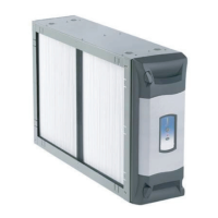
MODES OF OPERATION
The whole house air cleaner can be connected in one of
two modes of operation; either a 24 V mode or a
communicating mode. To know how the whole house air
cleaner is set up, reference Figure 1a to find the amber
light.
A steady amber light indicates that the unit is wired in
the 24 V mode.
A blinking amber light indicates that the unit is wired in
the communicating mode.
No light present means that the unit is not connected.
Plug Power Cord
in here
Power Button
Amber Light
 Loading...