Whole House Electronic Air Cleaner
ALL phases of this installation must comply with NATIONAL, STATE AND LOCAL CODES
IMPORTANT — This Document is customer property and is to remain with this unit.
Please return to service information pack upon completion of work.
Service Facts
This information is for use by individuals having adequate
backgrounds of electrical and mechanical experience. Any
attempt to repair a central air conditioning product may re-
sult in personal injury and/or property damage. The manu-
facturer or seller cannot be responsible for the interpreta-
tion of this information, nor can it assume any liability in con-
nection with its use.
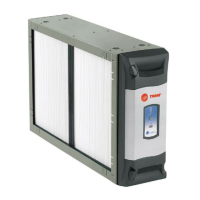
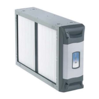
CELLS. Allows access to the COLLECTION CELLS, FIELD
CHARGER and PRE-FILTER.
6) TRANSFORMER - supplies 24 Volts to the indoor unit and Air
Cleaner
(not available with 50 Hz units)
7) 24 VOLT POWER / CONTROL CABLE
8) GASKET, LITERATURE AND HARDWARE PACKET
9) UPFLOW AIR HANDLER BAFFLE - This baffle is only included
with Air Handler models. See note below.
NOTE: Be careful not to discard the baffle. It is located under
the collection cells in the shipping box.
22
22
2
33
33
3
44
44
4
55
55
5
77
77
7
66
66
6
88
88
8
33
33
3
11
11
1
22
22
2
33
33
3
RECONNECT ALL GROUNDING DEVICES.
All parts of this product that are capable of conducting elec-
trical current are grounded. If grounding wires, screws,
straps, clips, nuts, or washers used to complete a path to
ground are removed for service, they must be returned to their
original position and properly fastened.
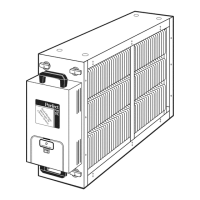
AIR
FLOW
1
WARNING
!
© Trane 2011
CAUTION
!
Air Handler Models
*FD175CLAH000D
*FD215CLAH000D
*FD235CLAH000D
*FD260CLAH000D
Downflow Furnace Models
*FD14DCLFR000D
*FD17DCLFR000D
*FD21DCLFR000D
*FD24DCLFR000D
Upflow Furnace Models
*FD145CLFR000D
*FD175CLFR000D
*FD210CLFR000D
*FD245CLFR000D
50 Hz Air Handler Models
TFD215CLAH005D
TFD235CLAH005D
TFD260CLAH005D
* May be "A" or "T"
99
99
9
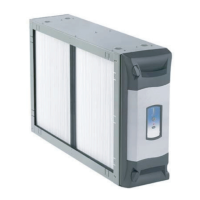
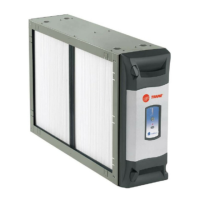
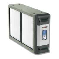
1) PRE-FILTER - traps large particles such as hair and lint before
they can enter the COLLECTION CELL section.
2) FIELD CHARGER - Charges the contaminants. Only to be
serviced by a qualified technician.
3) COLLECTION CELL (2) - removes and collects very small
impurities from the air.
4) CABINET - mounts between the furnace/air handler and return
air duct work and houses the COLLECTION CELLS, FIELD
CHARGER and PRE-FILTER.
5) POWER DOOR - the solid state power supply components
that convert the 24 Volt AC to the high-voltage, direct current
required to power the FIELD CHARGER and COLLECTION
11
11
1
COMPONENTS OF THE AIR CLEANER
EAC- SF- 13