10 Numbers in [brackets] are for 50 Hz international systems. Pub. No. 18-HE53D1-11
Installer’s Guide
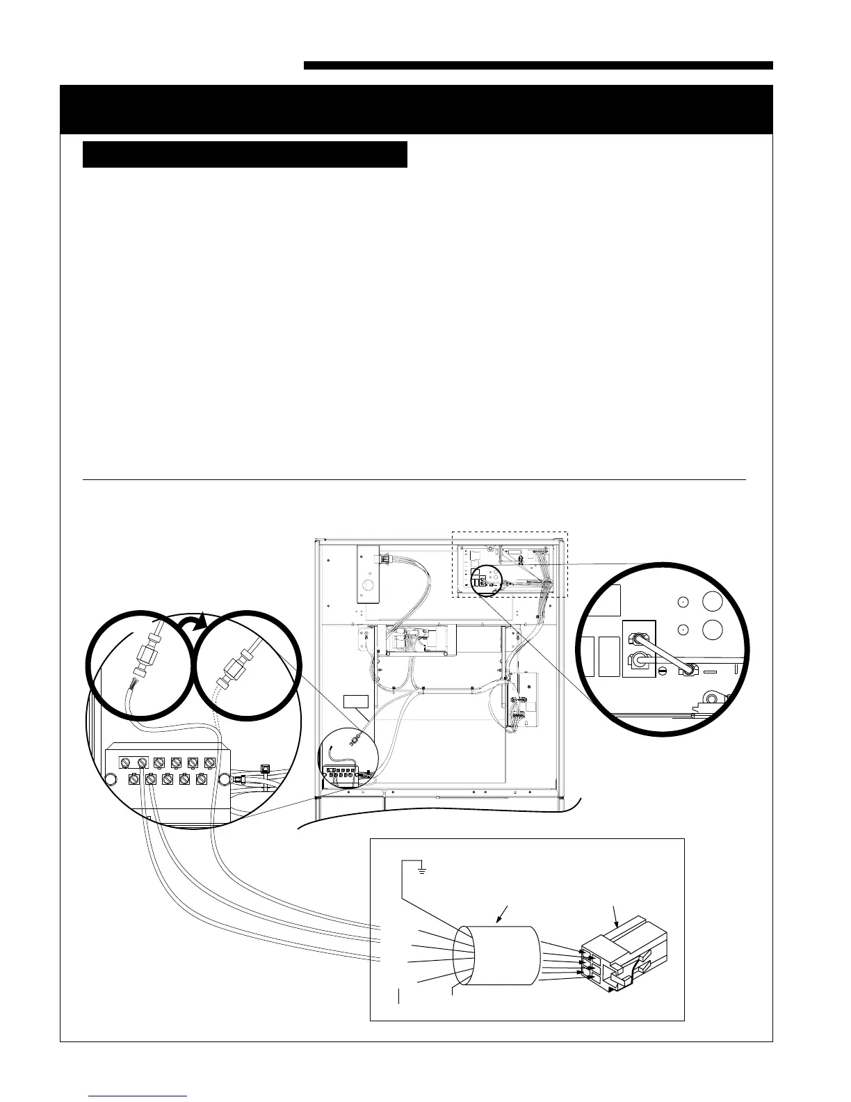
Control box panel cover
(Shown removed)
PCB Detail
Indoor Unit
24V
Terminal
Strip Detail
EAC
R
24V RED
jumper wire
from EAC to R
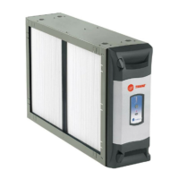
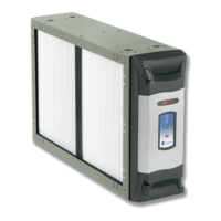
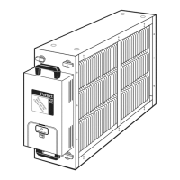
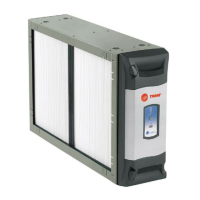
For use with Whole House
Air Cleaner
RED
BLUE
GREEN
BLACK
GRD
Air Cleaner
Plug
BROWN /
Future Use
Power / Control
Wiring Cable and Plug
Unused
Detach female spade terminal
from white EAC wire and
crimp to green wire
BEFORE AFTER
GREEN
GREEN
WHITE
WHITE
WHITE
BK R
O G Y1 Y2
D
B W1 W2 W3
GREEN
WHITE
EAC
WARNING
!
HAZARDOUS VOLTAGE! DISCONNECT ALL ELECTRIC
POWER, INCLUDING REMOTE DISCONNECTS BEFORE
SERVICING. FOLLOW PROPER LOCKOUT/TAGOUT
PROCEDURES TO ENSURE THE POWER CAN NOT BE
INADVERTENTLY ENERGIZED. FAILURE TO
DISCONNECT POWER BEFORE SERVICING COULD
RESULT IN DEATH OR SERIOUS INJURY.
PROCEDURE:
1) Remove electrical power going into the air handler.
2) On the communicating systems air handler, remove
the blower access panel.
3) Remove the communicating control box cover.
4) Locate the red jumper wire which is attached from
EAC to R on the Communicating Systems PCB.
Confirm it is connected. If there is not a jumper wire
installed, then one must be installed in this location
in order for the air cleaner to function properly.
5) Replace the Communicating control box cover.
6) Locate the white wire coming from the
Communicating System Air Handler PCB labeled
“EAC”. The wire will have a male spade terminal
connected to it and a female spade terminal
inserted into the male terminal. Remove the
female spade terminal and crimp it to the green
wire on the air cleaner harness.
7) Connect the green wire from the air cleaner
harness to the white wire on the Communicating
Systems Air Hand nected to the metal air handler
chassis.
10) Replace the blower access panel.
11) Reconnect electrical power to the air handler.
ELECTRICAL CONNECTIONS TO A COMMUNICATING SYSTEM AIR HANDLER
IN CONVENTIONAL 24 V MODE
 Loading...