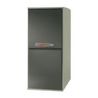
Do you have a question about the Trane TUHMD120ACV5VA and is the answer not in the manual?
Essential safety precautions including carbon monoxide, fire, explosion, and electrical hazards.
Details the routing of vacuum hoses for furnace operation and diagnostics.
Describes the components and layout within the burner box assembly.
Illustrates the user interface display and navigation for accessing settings.
Displays operational status, system information, faults, and alerts.
Allows configuration of various furnace operating parameters and settings.
Explains pressure switch roles and the furnace ignition sequence.
Details furnace response to W1, W2, and single-stage heating calls from 24VAC thermostats.
Describes continuous fan operation for heating and cooling cycles.
Guides on performing basic operational tests of the furnace via the user interface.
Outlines procedure for setting manifold gas pressure for optimal furnace performance.
Demonstrates correct technique for measuring manifold gas pressure referencing the burner box.
Explains the purpose and importance of the Personality Module for furnace operation.
Describes setting furnace for standalone operation with user-defined duty cycles.
Explains configuring contingency mode using a 24VAC comfort control.
Details IFC learning optimal speeds for pressure switches PS1 and PS2.
Outlines learning routine for PS-3, related to high heat operation.
Specifies timing for indoor blower operation during heating and cooling cycles.
Annual inspection checklist for furnace installation integrity and safety.
Guidelines for cleaning or replacing furnace filters based on usage and season.
Recommendations for blower maintenance, including cleaning and bearing lubrication.
Maintenance procedures for cleaning furnace burners for optimal performance.
Inspection and cleaning recommendations for the heat exchanger and flue pipe.
Explains the meaning of various LED flash codes and their corresponding faults.
Identifies components and connections on the Integrated Furnace Control board.
Lists diagnostic codes indicated by the furnace's LED flash patterns.
Overview of the Integrated Furnace Control board and its connection points.
Provides CFM and Watt data for heating operation at various static pressures.
Details CFM and Watt data for cooling operation at various static pressures.
Detailed explanations for various fault codes indicated by LED flashes and their groups.
Explains the meaning of Green, Red, and Amber LEDs on the IFC board.
Initial steps and guidance for beginning the troubleshooting process.
Labeled diagram of the IFC board showing connections and indicators.
A comprehensive list of LED flash codes and their corresponding error messages.
Flowchart for initial troubleshooting based on power and interface status.
Troubleshooting steps for "Retry LO" faults, focusing on ignition and gas pressure.
Diagnosing issues related to pressure switches (PS1, PS2, PS3) and inducer motor.
Troubleshooting for high limit, auxiliary limit, and roll out limit switch errors.
Steps to diagnose blower wheel rotation and external static pressure problems.
Checks for correct burner orifices, LP kit, and flue piping restrictions.
Verifies burner flame direction, combustion air blower, and heat exchanger airflow.
Diagnosing flame sensing errors, including gas valve and drip leg checks.
Troubleshooting steps for incoming voltage polarity and ground connection issues.
Diagnosing faults related to the ignitor, triac, and associated wiring.
Troubleshooting procedures for errors related to the external gas valve circuit.
Diagnosing low flame sensor current issues, including sensor positioning.
Diagnosing inducer limit faults, focusing on venting system and limit switch checks.
Troubleshooting steps for various communication faults between IFC and controls.
Guidance on diagnosing and resolving issues with the serial motor.
Diagnosing issues related to system clock faults and communication mismatches.
| Model | TUHMD120ACV5VA |
|---|---|
| Type | Gas Furnace |
| Heating Capacity | 120, 000 BTU |
| Blower Motor | Variable Speed |
| Fuel Type | Natural Gas |
| Stages | Two-Stage |
| AFUE Rating | 96% |
| Input Voltage | 120V |
| Filter Size | 20 x 25 x 1 |
| Blower Motor Type | ECM |


 Loading...