18-GE01D1-9 9
Installer’s Guide
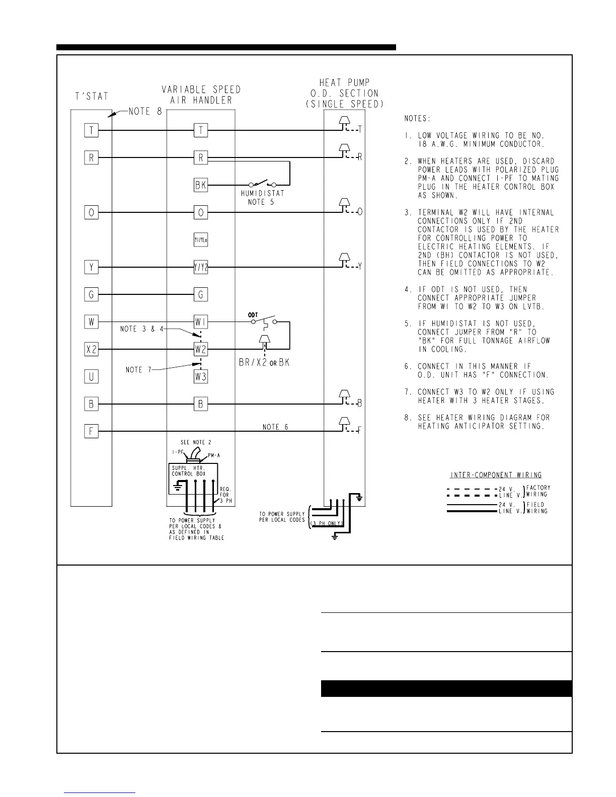
TWE-E AIR HANDLERS WITH SINGLE STAGE HEAT PUMP
From Dwg. No. B801077
H. CONTROL WIRING
1. Connect wiring between indoor unit, outdoor unit and
thermostat. The use of color-coded low-voltage wires is
recommended.
2. A low voltage terminal board is provided for control
wiring, and is located on the left side of the cross brace
in the center of the unit.
3. Field wiring diagrams are provided which show the
low voltage wiring hookup for a single speed cooling
only system (with supplementary heaters) and a heat
pump system (with supplementary heaters). Plug in
type electrical connectors are provided for use with
supplementary heaters.
IMPORTANT:
When supplementary heaters are installed, inspect to insure
that all packaging material has been removed.
I. AIRFLOW ADJUSTMENT
▲
CAUTION
!
Disconnect power to the air handler before changing dip
switch positions. Failure to follow this procedure may result
in equipment damage.