34
VAV-SVX08R-EN
supplied to the motor. Short and long flashes are used
to indicate values from 0 to 100 percent.
• 0% is displayed as an off LED.
• 1 – 99% are represented by a series of long flashes
followed by short flashes, whereas each long flash
adds 10% and each short flash adds 1%.
• 100% is displayed as a constantly lit LED.
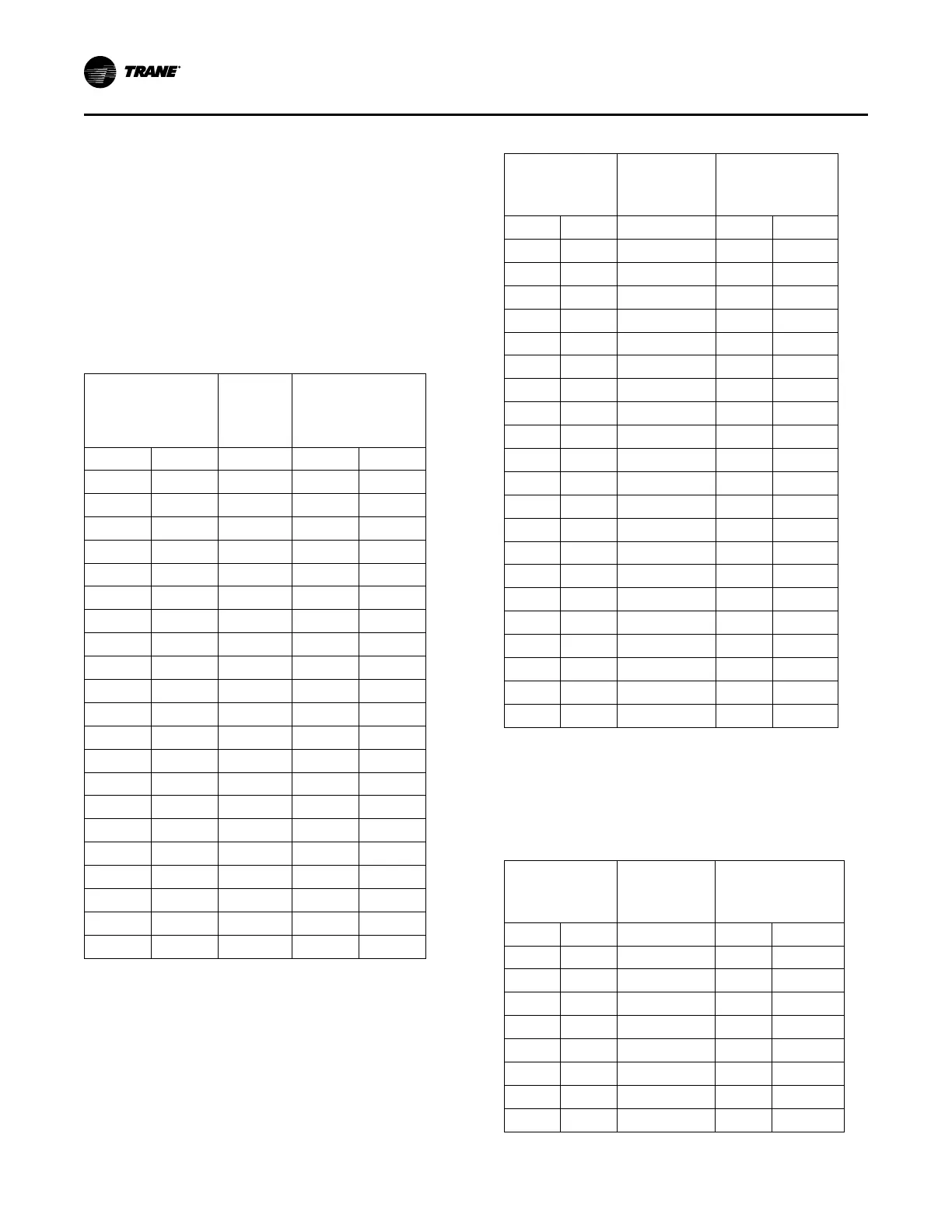
The following tables provide mapping from input
signal to fan airflow for each fan type and size.
Additional fan settings can be determined by
interpolating from the tables.
Table 12. VPxF 03SQ ECM CFM
Airflow
(Min CFM: 160, Max
CFM: 1085)
Trane
Controller
PWM
Signal
(a)
ECM Control Board
Signal
(b) (c)
CFM
L/s
% Setting
0-10V 2-10V
160 76 0% 0.0 2.0
206 97 5% 0.5 2.4
253 119 10% 1.0 2.8
299 141 15% 1.5 3.2
345 163 20% 2.0 3.6
391 185 25% 2.5 4.0
438 206 30% 3.0 4.4
484 228 35% 3.5 4.8
530 250 40% 4.0 5.2
576 272 45% 4.5 5.6
623 294 50% 5.0 6.0
669 316 55% 5.5 6.4
715 337 60% 6.0 6.8
761 359 65% 6.5 7.2
808 381 70% 7.0 7.6
854 403 75% 7.5 8.0
900 425 80% 8.0 8.4
946 447 85% 8.5 8.8
993 468 90% 9.0 9.2
1039 490 95% 9.5 9.6
1085 512 100% 10.0 10.0
(a)
% setting from Trane unit controller via pulse width modulating
signal or ECM control board with manual fan speed adjust setting.
(b)
ECM control board with 0-10 VDC fan modulation input and separate
fan on/off binary input required.
(c)
ECM control board with 2-10 VDC, has combined fan on/off and
modulation input where fan comes on when signal rises to 2 VDC and
goes off when signal falls to 1 VDC.
Table 13. VPxF 04SQ ECM CFM
Airflow
(Min CFM: 220,
Max CFM: 1510)
Trane
Controller
PWM Signal
(a)
ECM Control
Board Signal
(b) (c)
CFM
L/s
% Setting
0-10V 2-10V
220 104 0% 0.0 2.0
285 134 5% 0.5 2.4
349 165 10% 1.0 2.8
414 195 15% 1.5 3.2
478 226 20% 2.0 3.6
543 256 25% 2.5 4.0
607 286 30% 3.0 4.4
672 317 35% 3.5 4.8
736 347 40% 4.0 5.2
800 378 45% 4.5 5.6
865 408 50% 5.0 6.0
929 439 55% 5.5 6.4
994 469 60% 6.0 6.8
1059 500 65% 6.5 7.2
1123 530 70% 7.0 7.6
1188 560 75% 7.5 8.0
1252 591 80% 8.0 8.4
1317 621 85% 8.5 8.8
1381 652 90% 9.0 9.2
1446 682 95% 9.5 9.6
1510 713 100% 10.0 10.0
(a)
% setting from Trane unit controller via pulse width modulating
signal or ECM control board with manual fan speed adjust setting.
(b)
ECM control board with 0-10 VDC fan modulation input and separate
fan on/off binary input required.
(c)
ECM control board with 2-10 VDC, has combined fan on/off and
modulation input where fan comes on when signal rises to 2 VDC and
goes off when signal falls to 1 VDC.
Table 14. VPxF 05SQ ECM CFM
Airflow
(Min CFM: 280,
Max CFM: 1850)
Trane
Controller
PWM Signal
(a)
ECM Control Board
Signal
(b) (c)
CFM
L/s
% Setting
0-10V 2-10V
280 132 0% 0.0 2.0
359 169 5% 0.5 2.4
437 206 10% 1.0 2.8
516 243 15% 1.5 3.2
594 280 20% 2.0 3.6
673 317 25% 2.5 4.0
751 354 30% 3.0 4.4
830 391 35% 3.5 4.8
UUnniitt SSeettuupp
 Loading...


