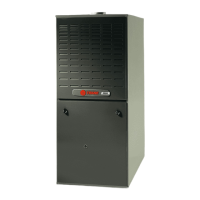
Do you have a question about the Trane XR 80 TUD1C100A9481A and is the answer not in the manual?
Lists the standard components and features included with the furnace.
Lists accessories and upgrades available for the furnace.
Detailed technical specifications including ratings, dimensions, and components for various models.
Table showing airflow (CFM) at different static pressures for various models.
Table correlating airflow (CFM) with temperature rise for different models.
Wiring schematic for furnaces operating in heating-only mode.
Wiring schematic for furnaces supporting both heating and cooling.
Diagram for connecting two furnaces for single-stage heating.
Diagram for connecting two furnaces for single-stage heating/cooling.
Visual representation with key dimensions for the TUD1 furnace models.
General wiring diagram illustrating electrical connections for gas furnaces.
Detailed schematic of electrical components and their interconnections.
| Brand | Trane |
|---|---|
| Model | XR 80 TUD1C100A9481A |
| Category | Furnace |
| Efficiency Rating | 80% |
| AFUE | 80% |
| Heating Capacity | 100, 000 BTU |
| Input BTU | 100, 000 BTU |
| Input Capacity | 100, 000 BTU |
| Output Capacity | 80, 000 BTU |
| Blower Type | Multi-speed |
| Blower Motor Type | PSC |
| Fuel Type | Natural Gas |
| Stages | Single-stage |
| Heat Exchanger Material | Aluminized Steel |
| Ignition Type | Hot Surface Ignition |
| Type | Gas |
| Furnace Type | Upflow |
| Warranty | 5-year limited warranty on parts |


 Loading...