Do you have a question about the Trane XR 80 TUD1A060A9361A and is the answer not in the manual?
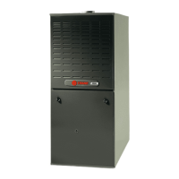
| Model Number | TUD1A060A9361A |
|---|---|
| Series | XR 80 |
| Type | Gas Furnace |
| Input BTU/h | 60, 000 |
| Output BTU/h | 48, 000 |
| Efficiency | 80% |
| Blower Type | Multi-speed |
| Ignition | Hot Surface |
| Heat Exchanger | Aluminized Steel |
| Stages | Single |
| Warranty | 5-year limited on internal functional parts |
Integrated System Control monitors flame presence and uses dual solenoid gas valve for safety.
Provides total control of furnace limits, blowers, gas valve, and self-diagnostics.
Provides tables detailing furnace airflow (CFM) at various static pressures for different models and speed taps.
Presents data correlating furnace airflow (CFM) with temperature rise for different models and CFM outputs.
Illustrates the field wiring connections for furnace operation in heating-only mode.


 Loading...