EC3 Service Manual Jan. 8, 2008 2
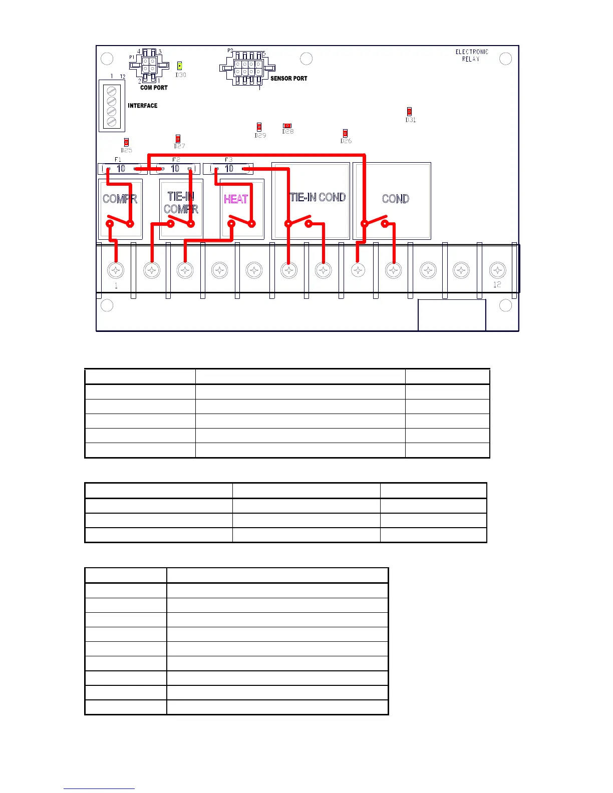
Figure 2 Relay Board Layout
Table 1 Relay Configuration
RELAY FUNCTION Currant rating
COMPR. Compressor clutch relay 10 amp
TIE-IN COMPR OEM tie-in compressor clutch relay 10 amp
HEAT Heat valve control relay 10 amp
TIE-IN COND. Tie-in condenser fan control relay 40 amp
COND. Condenser fan control relay 40 amp
Table 2 Fuse List
Fuse Description Rating
F1 Comp. Clutch fuse 10 amp
F2 Tie-in Comp. clutch fuse 10 amp
F3 Heat relay output fuse 10 amp
Table 3 Terminal Configuration
TERMINAL FUNCTION
1 Compressor clutch output
2 Tie-in compressor clutch output
3 Heat control relay output (optional)
4 Dash signal input
5 Ignition power input
6 Tie-in condenser power input
7 Tie-in compressor power output
8 Condenser power input
9 Condenser power output
 Loading...