Do you have a question about the Transcell Technology TI-500E SS and is the answer not in the manual?
Information regarding compliance with FCC rules for digital devices and potential radio frequency interference.
Environmental and electrical power considerations before installing the weight indicator.
Instructions for connecting the load cell cable to the indicator's main board assembly.
Details on connecting the serial I/O device and the power supply to the indicator.
Introduction to the indicator's configuration menus: Setup ('F') and User ('A').
Steps to enter the Setup ('F') and User ('A') menu modes using the indicator's controls.
Explanation of the two-level menu hierarchy and navigation keys used for configuration.
Detailed descriptions of parameters within the Setup menu (F1-F10).
Step-by-step instructions for specific setup procedures like Fine-tune 4-20 mA output (F23).
Detailed descriptions of parameters within the User menu (A1-A34).
Guides for configuring user-specific settings such as ID Number Entry and Line Feeds.
General information about the importance and types of calibration for the indicator.
Procedure for performing zero calibration, ensuring the scale is empty and stable.
Procedure for performing span calibration using known test weights.
How to view recorded zero and span calibration values from previous procedures.
Procedure for manually entering zero and span calibration values due to memory loss.
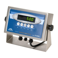
Explanation of the 6-digit LED display, annunciators, and function keys.
Details on the functionality of each key, including units toggle and zero/tare functions.
Step-by-step guide for selecting units and performing a standard weight measurement.
Instructions for Piece Counting Mode and Peak Hold Mode.
Configuration for Remote Display Mode and procedure for Legal for Trade Sealing.
Description of different serial communication modes like Demand Duplex and Continuous Duplex.
Details on data formats for serial communication, including Text Print Ticket and Condec strings.
| Material | Stainless Steel |
|---|---|
| Readability | 0.1 lb / 0.05 kg |
| Protection Class | IP65 |
| Display | LCD |
| Power | AC Adapter |
| Operating Temperature | 14°F ~ 104°F / -10°C ~ 40°C |