Antenna WireAntenna Wire
Power Wire
Power Wire
Antenna Wire
Antenna Wire
Power Wire
Power Wire
to accessoryto accessory
Y-harness
Y-harness
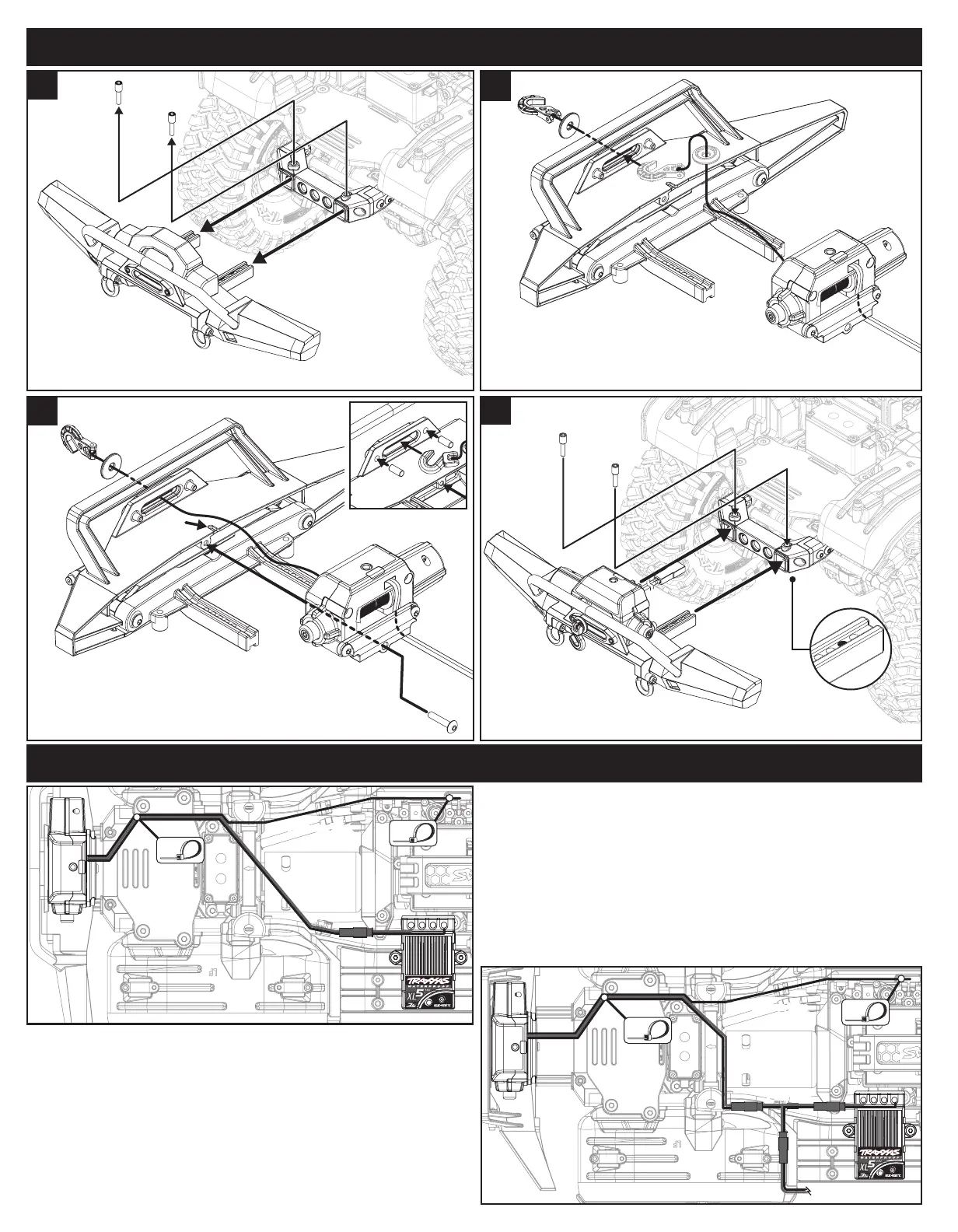
Route the power wire and antenna wire from the winch along the right
chassis rail to the front shock tower (Fig. 3). Continue to route the antenna
wire along the right chassis rail and secure it to the loop on the servo mount
with one of the included zip ties.
Route the power wire through the shock tower and over to the XL-5 HV
electronic speed control (on the XL-5 HV, the red connector is direct output
voltage from the battery; the maximum voltage that the winch can accept is
4s LiPo). Note: Be sure to allow adequate body clearance so that it doesn’t
rub against or cut the wires.
Secure any excess length of the wires with the existing left and right front
wire clips and the remaining zip ties to prevent contact with any moving
parts or assemblies.
Plug the red male connector from the speed control into the red female
connector from the winch.
If you have another accessory installed, such as an external BEC or
LED lighting,
plug the red male connector from the speed control into
the red female connector from the included Y-harness as shown in Fig. 4.
Plug the other red male connectors from the Y-harness into the red female
connectors from the winch and the other accessory.
• For custom installations (Fig. 5)
The winch may be mounted to a at surface and attached with up to four
2.5x10mm screws through the bottom of the winch. The maximum depth
of the screws into the winch is 9.5 mm. Remove the winch mount and
install the included 2.5x12mm CS in the winch housing prior to installation.
2.5x12mm
CS
2.5x12mm
CS
2.5x10mm CS
2.5x10mm CS
• If your front bumper does not include a built-in fairlead (Fig. 6)
Thread the winch hook and washer through the included fairlead and
install it on the winch with the supplied 2.5x10mm CS.
Binding the wireless remote to the winch
Note: The wireless remote has two channels (1 or 2) that can be used to
operate two separate winches independently. The wireless remote needs
to be bound to the winch in order to operate.
Select Channel
Pull the clear tab out of the remote to allow the battery to connect.
1. Press and release the Channel Select button and the activity LED on
the remote will blink the current channel (1 or 2 blinks).
2. Press and hold the Channel Select button for 4 seconds to alternate
between channels 1 and 2.
Binding
1. Press and hold the Bind button on the winch for 3 seconds; the status
LED on the winch will turn solid red.
1
Install the new front bumper.
4
3
Install the winch/winch mount on the new front bumper.
Place the winch power wire into the slot on the bumper.
Note: Use the included 3x6mm pins in the fairlead if you are
installing the winch/winch mount on an existing front bumper.
2.6x8mm
BCS
Slot
Thread the winch hook and washer through the
fairlead on the new front bumper (see chart above for compatibility).
Note: Turn the washer horizontal to t it through the fairlead.
2
Remove the existing front bumper from the chassis.
1
INSTALLATION OPERATION
CUSTOM INSTALLATIONS
WIRING DIAGRAM
3x6mm
Pin
• Replacing the winch line
(Fig. 7)
1. Thread the winch line into the hole in the spool on the winch. Tie a
knot in the end of the line to secure it to the spool. Note:
The winch
line is available in other colors to customize the look of your vehicle (part
#8864 grey, 8864R red, 8864X blue, each sold separately).
2. Insert the other end of the line through the washer and then tie it to
the winch hook as shown in Fig. 5.
• Installing the winch line retainer
(Fig. 8)
Install the included line retainer on the winch hook as shown below to
help prevent the line from slipping o the hook.
Winch Hook
Fig. 7
2. Press and release either the Line In or Line Out button on the wireless
remote. The status LED on the winch will turn o indicating that the
winch and remote are now bound and ready for use.
Winch operation
1. To operate the winch, press the Line In or Line Out button on the
wireless remote to control the line feed.
2. Release the Line In or Line Out button on the remote to stop the
winch. The automatic brake will prevent the winch from unwinding
while the line is under tension.
Freespool Feature
The Traxxas winch is equipped with a Freespool feature that allows you
to manually pull the winch line out for fast operation. Press and hold the
freespool button (see Fig. 2) while pulling the line out to the desired length.
Always use the wireless remote to wind the line back on the winch spool.
Overload protection mode
If the winch stops working during operation and the status LED on the
winch starts to slowly blink red, it has entered overload protection mode.
Allow the winch components to cool for a few minutes before continuing.
Fig. 5
Fig. 6
Fig. 8
32
2
CAUTION: RISK OF INJURY!
Moving parts can cause injury. Keep hands and objects
clear during operation.
Fig. 3
Fig. 4
 Loading...