24
•
XRT ULTIMATE
Once you become familiar with driving your model, you might need
to make adjustments for better driving performance.
Adjusting Gear Mesh
Incorrect gear mesh is the most common cause of stripped spur
gears. XRT Ultimate makes improper gear mesh virtually impossible.
A pin system helps set the motor in the proper place according to
the pinion and spur gear that are selected.
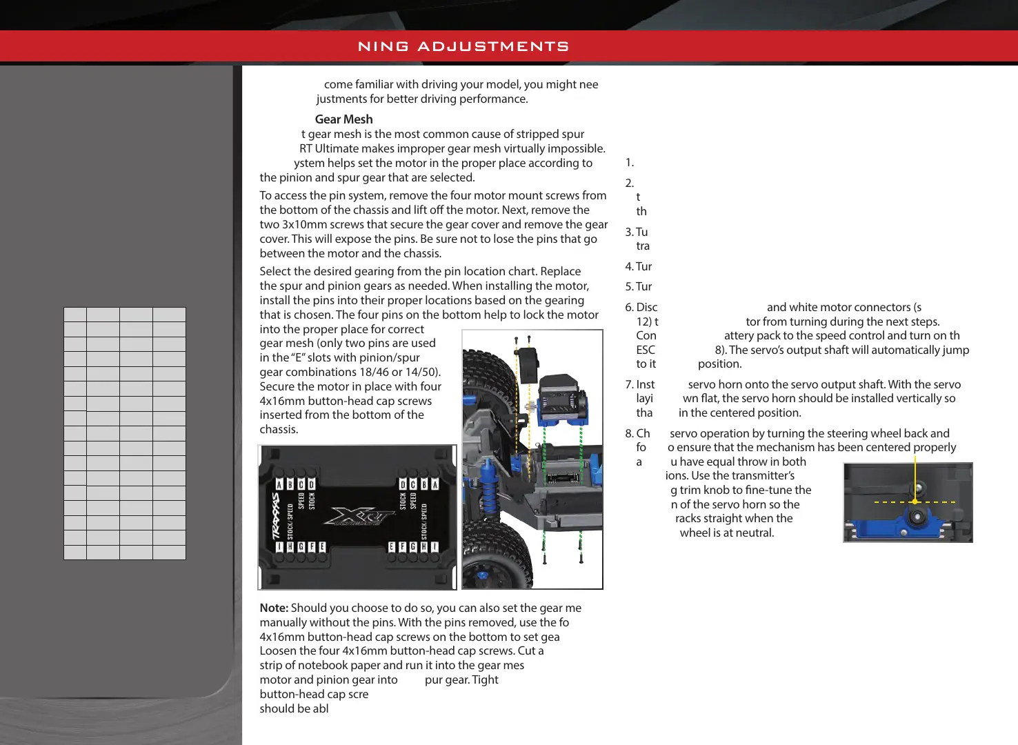
To access the pin system, remove the four motor mount screws from
the bottom of the chassis and lift o the motor. Next, remove the
two 3x10mm screws that secure the gear cover and remove the gear
cover. This will expose the pins. Be sure not to lose the pins that go
between the motor and the chassis.
Select the desired gearing from the pin location chart. Replace
the spur and pinion gears as needed. When installing the motor,
install the pins into their proper locations based on the gearing
that is chosen. The four pins on the bottom help to lock the motor
into the proper place for correct
gear mesh (only two pins are used
in the “E” slots with pinion/spur
gear combinations 18/46 or 14/50).
Secure the motor in place with four
4x16mm button-head cap screws
inserted from the bottom of the
chassis.
Note: Should you choose to do so, you can also set the gear mesh
manually without the pins. With the pins removed, use the four
4x16mm button-head cap screws on the bottom to set gear mesh.
Loosen the four 4x16mm button-head cap screws. Cut a narrow
strip of notebook paper and run it into the gear mesh. Slide the
motor and pinion gear into the spur gear. Tighten the four 4x16mm
button-head cap screws, and then remove the strip of paper. You
should be able to run a fresh strip of paper through the gears
without binding them.
Centering Your Servo
If you have removed the servo horn from your XRT Ultimate’s
steering servo, or the servo has been removed for service or cleaning,
the servo must be re-centered prior to installation of the servo horn
or installation of the servo.
1. Remove the servo horn from the steering servo.
2. Connect the steering servo to channel 1 on the receiver. Connect
the electronic speed control (ESC) to channel 2. The white wire on
the servo lead is positioned toward the receiver’s LED.
3. Turn the transmitter power switch on. Make certain the
transmitter’s batteries are not depleted.
4. Turn o TSM (see page 17).
5. Turn the transmitter’s steering trim knob to the center “0” position.
6. Disconnect both the blue and white motor connectors (see page
12) to prevent the motor from turning during the next steps.
Connect a fresh battery pack to the speed control and turn on the
ESC (see page 18). The servo’s output shaft will automatically jump
to its center position.
7. Install the servo horn onto the servo output shaft. With the servo
laying down at, the servo horn should be installed vertically so
that it is in the centered position.
8. Check servo operation by turning the steering wheel back and
forth to ensure that the mechanism has been centered properly
and you have equal throw in both
directions. Use the transmitter’s
steering trim knob to ne-tune the
position of the servo horn so the
model tracks straight when the
steering wheel is at neutral.
BASIC TUNING ADJUSTMENTS
PIN LOCATION CHART
Spur Gear
Pinion Gear
46 50 54
11
- - A, E
12
- - A, F
13 - - B, F
14
- E B, G
15
- A, E C, G
16
- A, F C, H
17
- B, F D, H
18 E B, G D, I
19
A, E C, G -
20
A, F C, H -
21
B, F D, H -
22
B, G D, I -
23 C, G - -
24
C, H - -
25
D, H - -
26
D, I - -
3x10mm
CS
4x16mm
BCS