2
230V
50Hz 0,75A
FUSE:T2,0A
120VAC
60Hz 1.5A
FUSE:
T3.0A SloBlo
SPEAKER EMU LATOR
(P
RE-MASTER)
D
Y
N
A
-
S
O
U
N
D
0
5
10
0
5
10
0
5
10
0
5
10
0
5
10
0
5
10
0
5
10
0
5
10
0
5
10
0
5
10
0
5
10
CHANN EL
SE
LECT
EXPANDERSCOOP
Traynor Guitar Amplifier
GAIN
1 2
INPUT
VOLUME
VOLUMEMIDDLE
BASS
TREBLE
MIDDL
E
BASSTREBLE
REVERB
MASTER VOLUM E
POWER
STANDBY
BRIG
HTNESSBOOST
CAUTION: REPLACE WITH
SAME TYPE FUSE AND RATING
AT
TENTION: UTILISER UN FUSIBLE DE
RECHANGE DE MEME TYPE ET CALIBRE
SEND
BALANCED
LINE OUT
PHONE S
/
LINE OUT
FOOTSWITCH
RTNCH. SELECT
/ BOOST
FUSE
ON
EXTENSIO N
SP
EAKER
SEND
TRIM
RE
TURN
TRIM
SPE
AKER
DEFEAT
LOOP THRU
EFFEC
TS
TIP: SEND
RING RTN
PARALLEL EFFECTS LOO P
POWER
DESIGNED & MANUFACTURED BY
YORKVILLE SOUND • Toronto, CANADA
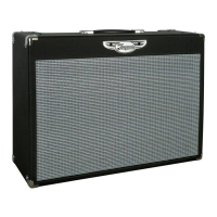
TRAYNOR YCV80
ValveCustomCustom
80
•
Q
U
A
L
I
T
Y
&
I
N
N
O
V
A
T
I
O
N
•
•
E
S
T
A
B
L
I
S
H
E
D
1
9
6
3
•
Yorkville
1
15
19
22
21
23
24 252618
2 4 65 8 9
11 1213
3
16
7
10
17
14
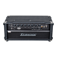
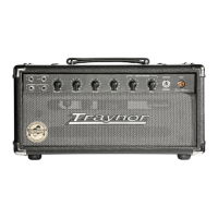
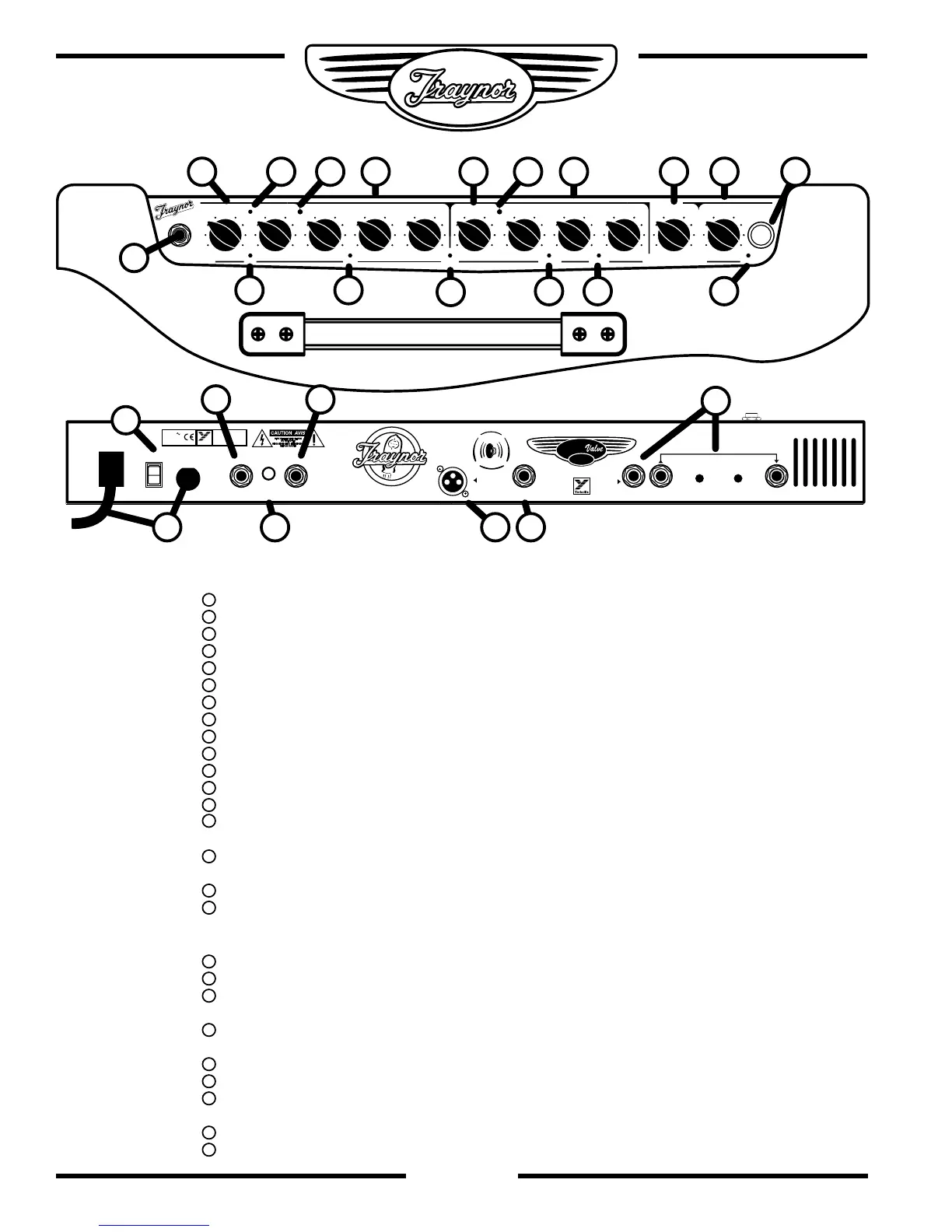
Chassis Layout
Top
Input jack – ¼ inch phone jack.
Channel 1 Gain & Volume Controls.
Channel 1 Boost Switch – Activates the boost circuitry.
Boost LED – Illuminated Red when the boost is active.
Channel 1 Indicator LED – Illuminates Yellow when active.
Channel 1 Tone Controls – Treble, Bass, & Middle.
Channel Select Switch – Channel 1 is optimized for lead, Channel 2 for clean
Channel 2 Volume Control.
Channel 2 Indicator LED – Illuminates Green when active.
Channel 2 Brightness Switch – Add sparkle to your clean sound.
Channel 2 Tone Controls – Treble, Bass, & Middle.
Master Volume- Controls overall volume of both channels.
Reverb Control – Adjusts the Accutronics® reverb level for both channels.
Standby Switch – Activates standby mode to keep the tubes warm while
the amp is not in use.
Power Indicator Jewel – Illuminates red when in Active mode, and yellow
when in Standby mode.
Scoop Switch – Adds mid scoop and big bottom end to Channel 1.
Expander Switch – Adds deep bottom and sparkling highs to Channel 2 sound.
Rear
Fuse and Power Cord
Power Switch.
Send / Rtn (Efx/Line) jacks – ¼ inch phone Input and Output jacks with
individual level controls for send and return
Channel Select Footswitch jack – uses a ¼ inch TRS standard latching dual-
footswitch.
Extension Speaker jack –1/4 inch phone jack.
Loop Thru – ¼ inch TRS jack for connecting effects pedals.
Direct Out – Balanced XLR output with speaker emulator compensation for
recording or direct connection to mixing consoles.
Headphone Output – ¼ inch phone jack with speaker emulator compensation.
Speaker Defeat – Disengages the signal from the power amplifier to the speakers.