2
INSTALLATION INSTRUCTIONS
WARNING: This Surge Guard device must be installed by a licensed electrician or by an RV dealer.
PROTECTING SOURCE AND GENERATOR POWER
1. Disconnect RV power cord from source power.
2. Locate the Surge Guard
®
next to the transfer switch. Unit should be
located where lights are clearly visible to the user.
MOUNTING IN RV COMPARTMENT
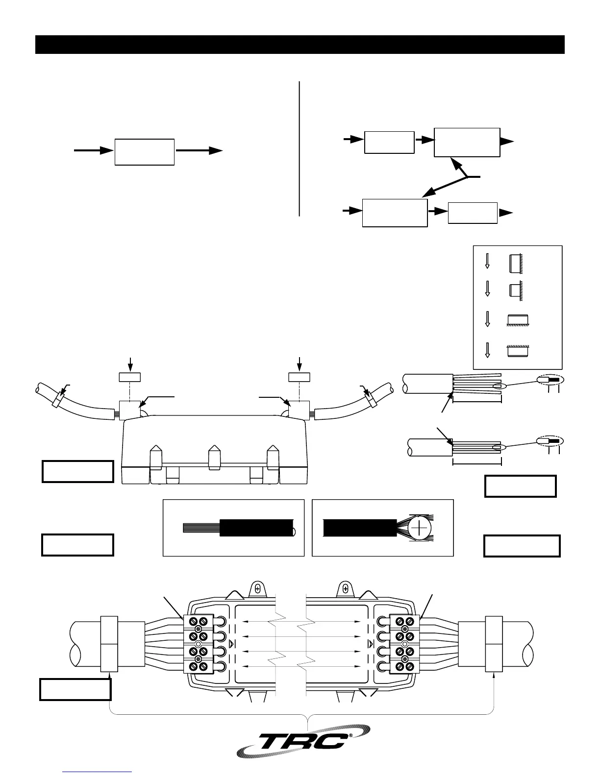
1. Position so LINE end is facing direction of incoming power cord.
2. Using #10 hardware, mount unit securely in place using molded mounting tabs.
3. Remove terminal block covers (Model 35530 only)
4. Route primary cable into position (over exposed terminals or into terminal block wells) - allowing enough slack to eliminate stress
or tension on cable connections to be made. (See Figure 2)
5. Cut power cord, strip back outer jacket as shown. (See Figure 3)
6. Install conductors as shown. (See Figures 4, 4A, 5 & 5A)
7. After connections are made, secure both line and load side cables. Use "U" clamps (not supplied) to prevent strain on terminal
connections. Recheck tightness of ALL connections.
8. Reinstall connector covers (Model 35530 only).
PROTECTING SOURCE POWER ONLY
1. Disconnect RV power cord from source power.
2. Locate the Surge Guard
®
in the RV's electrical compartment. Unit
should be located where lights are clearly visible to the user.
POWER
SOURCE
INPUT
LINE LOAD
OUTPUT
DISTRIBUTION
PANEL
Surge
Guard
POWER
SOURCE
DISTRIBUTION
PANEL
Surge
Guard
Transfer
Switch
POWER
SOURCE
DISTRIBUTION
PANEL
Surge
Guard
Transfer
Switch
ALTERNATE
(Generator)
NOTE: Additional cable used must be electrically
equivalent to original equipment.
GRAVITY
GRAVITY
GRAVITY
GRAVITY
WALL
WALL
WALL/FLOOR
WALL
YES
YES
NO
YES
MOUNTING POSITION
FIGURE 2
LOADLINE
"U" Clamp
(not supplied)
INPUT
7" MAX.
(clamp to terminal)
(TERMINAL COVER)
OUTPUT
(TERMINAL COVER)
NO TENSION OR PULL
ON WIRE TERMINATION(S)
7" MAX.
(terminal to clamp)
"U" Clamp
(not supplied)
FIGURE 3
TRIM CABLE
FILLERS FLUSH TO
CABLE JACKET
STRIP EACH CONDUCTOR
INSULATION 1/2" AS SHOWN.
1/2"
1/2"
4 WIRE
240V/50Amp
3 WIRE
120V/30Amp
↔
↔
3-4"
3-4"
FIGURE 4
50A Model 35550
30A Model 35530
FIGURE 4A
W
H
I
T
E
G
R
E
E
N
R
E
D
(GND)
B
L
A
C
K
GREEN
RED
WHITE
BLACK
G
R
E
E
N
GREEN
RED
WHITE
BLACK
(GND)
W
H
I
T
E
R
E
D
B
L
A
C
K
Do NOT split strands. Slide
into terminals of block housing
INSERT PREPARED WIRES. STRIPPED
ENDS MUST BE CONTAINED INSIDE
TERMINAL BLOCK HOUSING.
INSERT PREPARED WIRES. STRIPPED
ENDS MUST BE CONTAINED INSIDE
TERMINAL BLOCK HOUSING.
LINE
(INPUT)
LOAD
(OUTPUT)
IMPORTANT NOTE: MAX TORQUE PER CONNECTION = 16 IN-LBS.
120/240V - 50A
MODEL# 35550
FIGURE 5