2 3
TECHNICAL SPECIFICATIONS
1. Plug the RV power cord into an approved RV receptacle.
2. Verify the delay indicator is ashing, and the line lights are green.
3. Once caution light stops ashing (this takes 128 seconds), verify RV
power is on.
NOTE: USING WITH TRC VOLTAGE REGULATOR
If using Surge Guard with TRC Voltage Regulator (10175 or 10176) the
voltage regulator should be positioned between the power pedestal (shore
power) and the Surge Guard.
WARNING: It is extremely important that the terminal covers
(Model 35530 only) are in place prior to applying power to the RV.
Failure to comply with these instrctions may result in a shock hazard.
OPERATING INSTRUCTIONS
TROUBLESHOOTING
FEATURES MODEL 35530 MODEL 35550
Operating Current 30 Amps 50 Amps
Operating Voltage 120 Volts 120/240 Volts
Maximum Watts 3600 Watts 12000 Watts
3 Mode Surge Protection Yes, L-N, L-G,N-G
Yes, L-N, L-N, L-G,
N-G, L-L
Energy Dissipation 2450 Joules 3850 Joules
Maximum Spike Current 6500A per MOV 6500A per MOV
Over/Under Voltage Protection Yes Yes
Voltage Range 132/102V 132/102V
Trip Time 8-10 seconds 8-10 seconds
High Neutral Current Trip N/A 130%
Time Delay for A/C 128 seconds 128 seconds
Reverse Polarity Protection Yes Yes
Voltage On Ground Check Yes Yes
Power Indicator Yes (1 line light) Yes (2 line lights)
Warranty 1 year 1 year
Corrosion Resistant Yes Yes
Easy Installation Yes Yes
Industrial Contactor Yes Yes
SYMPTOM CAUSE SOLUTION
Caution light is
ashing
1. Reverse polarity or
voltage on ground
condition is present at
the power source.
2. Surge Guard mis-wired
on the line side.
3. Open ground circuit on
the line side
1. Move RV to new
electrical source.
2. Match colors
on terminals
with colors on
conductors.
3. Move RV to new
electrical source.
L1 and/or L2 is
red or off, and
caution light is
ashing
1. Only partial power at
50 Amp source.
2. No power at source
1. Move to a new
source
2. Use inverter or
generator power
SURGE light
is on
1. Built-in surge
protection has been
sacriced to protect
your equiptment and is
no longer functioning.
2. Other features will
still function, but it
is recommended to
replace unit.
INDICATOR LIGHT CHART
MODEL 35530
CONDITION
DESCRIPTION
INDICATOR LIGHT STATUS
RV POWER
LINE 1 DELAY/CAUTION
Normal Conditions green off on
Startup Condition on ashing off
Reverse Polarity on ashing off
Open Ground on ashing off
Voltage on Ground on ashing off
Over or Under Voltage red ashing off
No Power at L1 off off off
MODEL 35550
CONDITION
DESCRIPTION
INDICATOR LIGHT STATUS
RV
POWER
LINE 1 LINE 2 DELAY/CAUTION
Normal Conditions green green off on
Startup Condition on on ashing off
Reverse Polarity on on ashing off
Open Ground on on ashing off
Voltage on Ground on on ashing off
Over or Under Voltage red red ashing off
Power to Line 1 Only on red ashing off
Power to Line 2 Only off off off off
No Power at Input off off off off
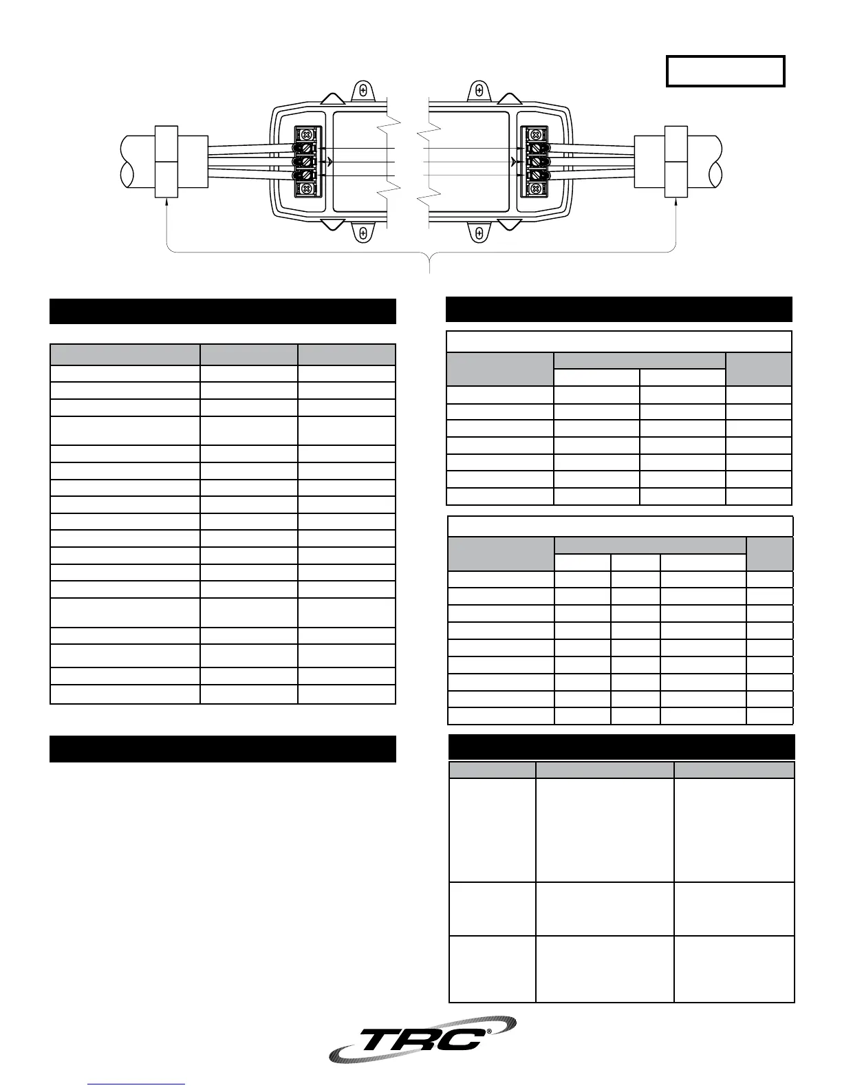
BLACK
GREEN
WHITE
BLACK
WHITE
GREEN
BLACK
GREEN
WHITE
LINE
(INPUT)
LOAD
(OUTPUT)
IMPORTANT NOTE: MAX TORQUE PER CONNECTION = 7 IN-LBS.
DO NOT EXCEED.
120V- 30A
MODEL# 35530
FIGURE 5A
 Loading...